

Fluorescent lamp lighting device
- Summary
- Abstract
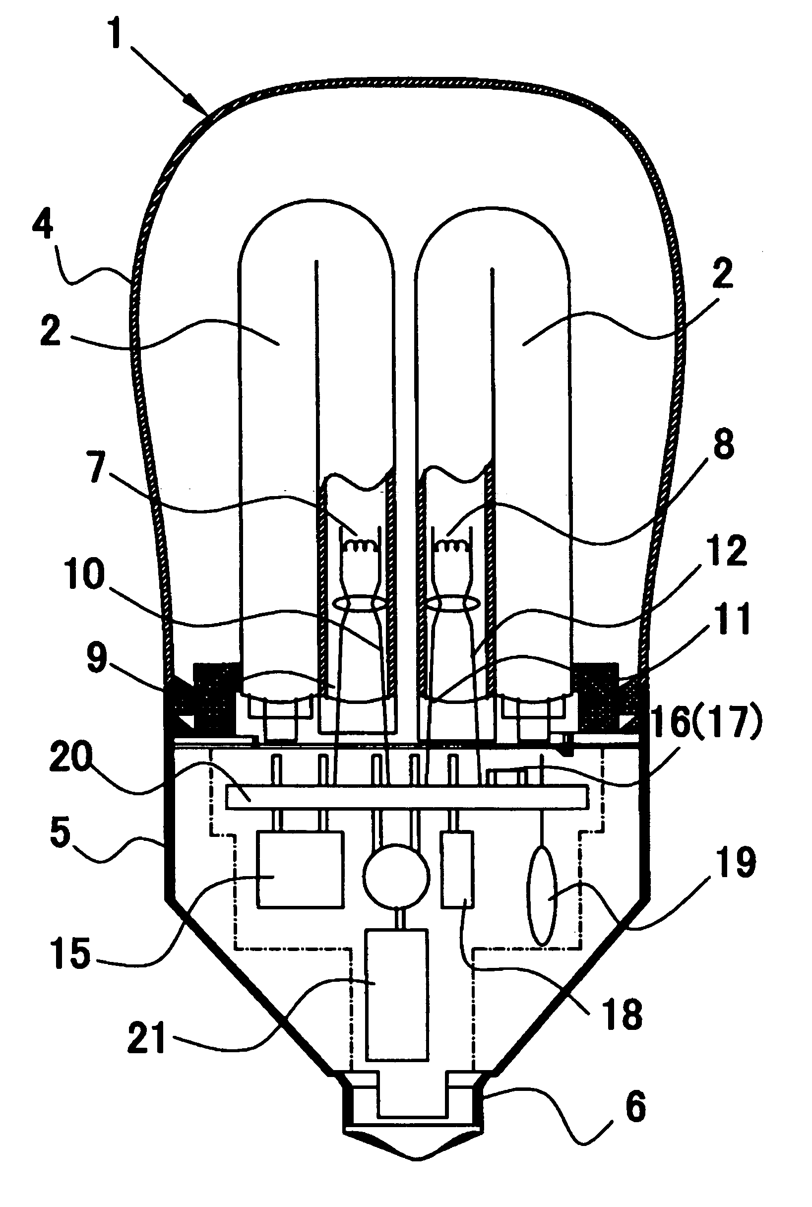
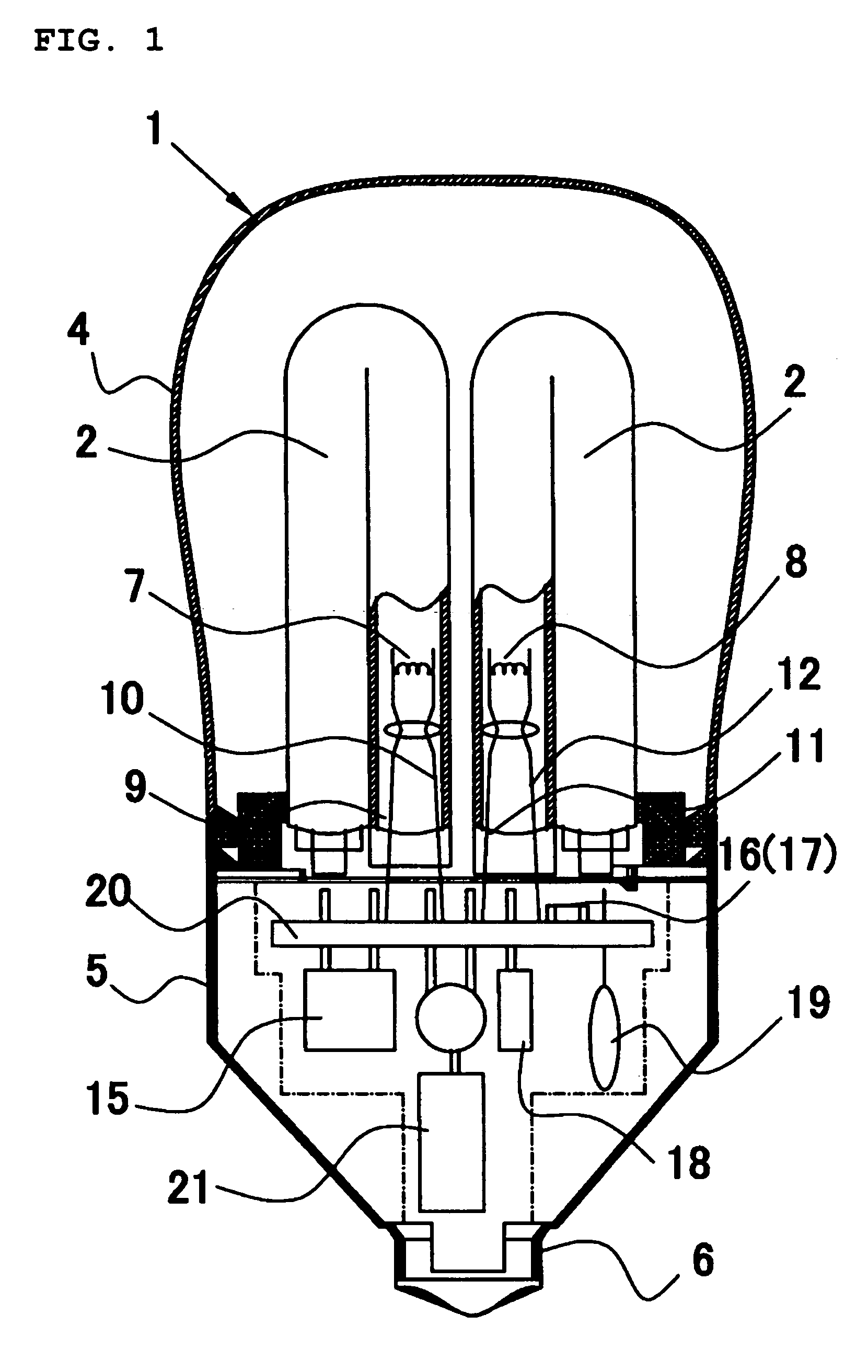
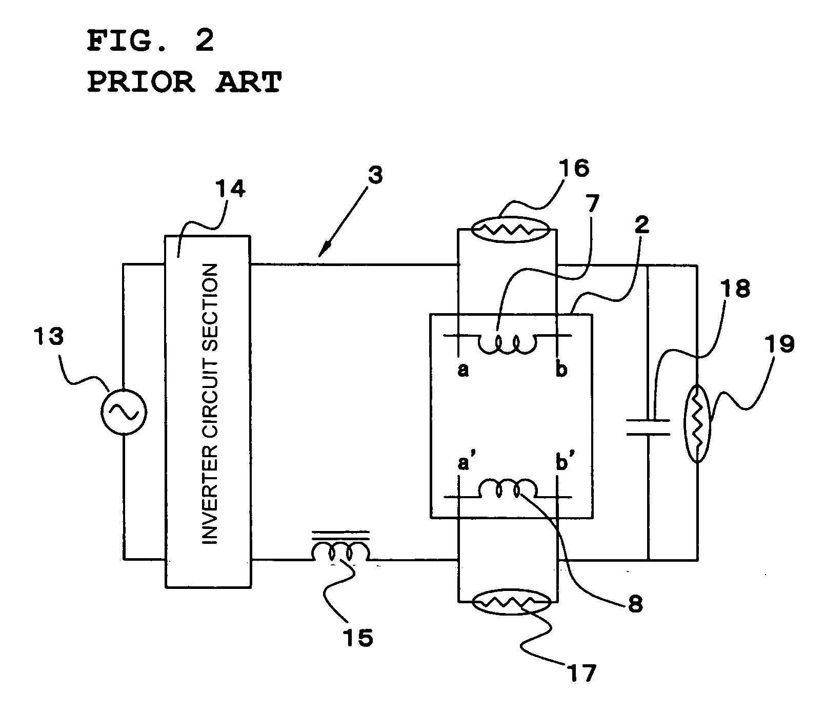
- Description
- Claims
- Application Information
AI Technical Summary
Benefits of technology
Problems solved by technology
Method used
Image

Examples
Embodiment Construction
Comparative 0 0 0 0 22 15 21 16 23 25 Example 2 Number of Cycles 11 12 13 14 15 16 17 18 19 20 First 0 0 0 0 9 13 17 16 17 18 Preferred Embodiment Second 0 0 0 0 0 0 0 0 0 0 Preferred Embodiment Comparative 27 25 28 35 34 38 32 37 33 39 Example 1 Comparative 25 17 17 16 19 26 18 18 29 28 Example 2
[0039] As is also clear from Table 1, when the reed-type NTC thermistor was used, glow discharge occurred within five cycles when either on the surface of the circuit substrate that faces the base side or on the surface facing the fluorescent light bulb side the reed-type NTC thermistor was mounted.
[0040] However, in a case where the surface-mount-type NTC thermistor was used, in the first preferred embodiment in which it was surface-mounted on the base side, glow discharge did not occur for up to 14 cycles, and in the second preferred embodiment in which it was surface-mounted on the fluorescent light bulb side, glow discharge did not occur even at 20 cycles.
[0041] It can be clearly seen f...
PUM
 Abstract
Description
Claims
Application Information