Disk substrate, mold apparatus for injection molding the same, and disk substrate taking-out robot

a technology for taking out robots and disk substrates, which is applied in the direction of instruments, manufacturing tools, light beam reproducing, etc., can solve the problems of deterioration of yield, limitation of servo mechanism servo performance, and product d

Inactive Publication Date: 2004-05-20
SONY CORP
View PDF4 Cites 5 Cited by
  • Summary
  • Abstract
  • Description
  • Claims
  • Application Information

AI Technical Summary

Benefits of technology

[0044] The disk substrate according to the present invention, constituted as described above, has an edge completely free of flash at least on the signal transfer surface side of the center hole, or even if the flash is generated, the flash can be suppressed to equal to or less than 10 .mu.m in height, so that the centering of the disk substrate by a positioning center pin of a spindle motor can be performed with high accuracy.
[0113] Therefore, according to the disk substrate taking-out apparatus 31, the sprue and gate remaining resin 23a is projected to the side of the opposite surface 25 of the disk substrate 23 when the movable die 3 is opened. Thus, notwithstanding the position of the sprue and gate remaining resin 23a relative to the disk substrate 23 is reverse to that in the case of the prior art shown in FIG. 27, the sprue and gate remaining resin 23a can easily be discharged in the direction of arrow a without generating any trouble and before the start of transfer of the disk substrate 23 onto the aligning machine (not shown) by the robot 32, by a method in which air is jetted from the air jet nozzle 34 of the robot 32 immediately after the disk substrate 23 is chucked by the suction pad 33 of the robot 32. Therefore, after the sprue and gate remaining resin 23a is discharged, the disk substrate 23 can be smoothly transferred onto the aligning machine (not shown) by the robot 32, to be aligned, in the same manner as in the prior art.(4) Description of Measurement Results of Eccentricity Amount of the Disk Substrate

Problems solved by technology

When the timing of the punching of the center hole 74 is delayed from the above-mentioned, strain due to punching and punch tailings are liable to be generated at the inner circumference of the center hole 74, and a disk substrate 73 with abnormal birefringence may be molded or gate cutting stroke may be varied, resulting in a defective product.
However, the servo performance of the servo mechanism has a limitation, and, particularly, it is important to restrain eccentricity of a spirally shaped groove and the center hole 74.
Although the flash 75 can be removed by a method of cutting by a reamer or the like, the generation of waste upon removal of the flash 75 and the increase in the number of working steps lead necessarily to deterioration of yield and an increase in cost.
The accuracy required of the shape of the fine roughness increases as the recording density of the disk increases, and, therefore, it is difficult to mold the disk substrate 73 even by the movable-side stamper.
Though the flash 75 does not have bad effects on the disk eccentricity at the time of chucking, waste might be generated through stripping of the flash 75 at the time of production, and the flash might adhere to the disk substrate 73 to thereby cause an increase in error, leading to a reduction in yield.

Method used


Image

  • Disk substrate, mold apparatus for injection molding the same, and disk substrate taking-out robot
  • Disk substrate, mold apparatus for injection molding the same, and disk substrate taking-out robot
  • Disk substrate, mold apparatus for injection molding the same, and disk substrate taking-out robot

Examples


second embodiment

(5) Description of Second Embodiment of the Mold Apparatus for Injection Molding the Disk Substrate

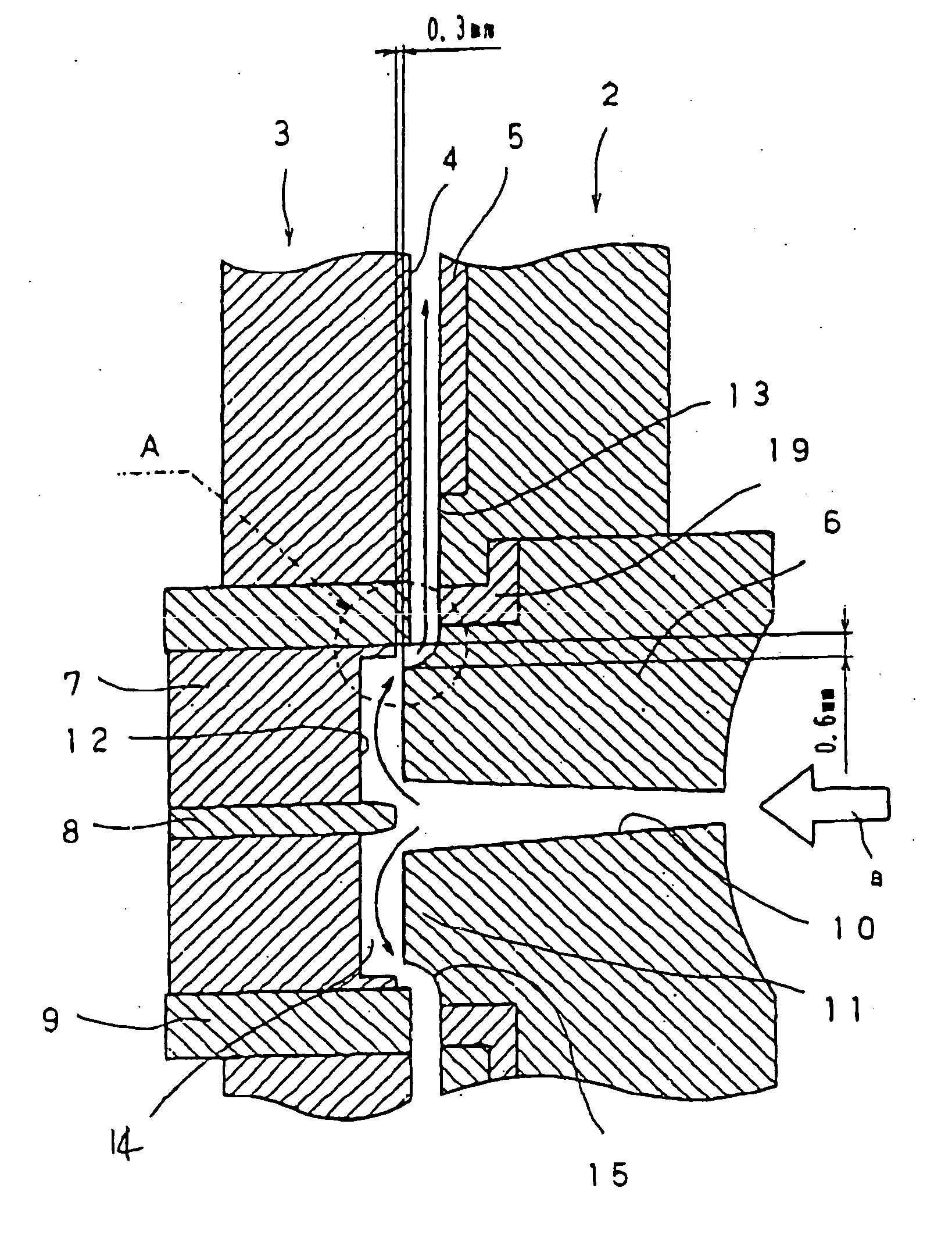
[0119] Next, referring to FIGS. 14 and 15, Second Embodiment of the mold apparatus 1 will be described. In this case, a second R surface molding portion (or a second C surface molding portion) 20 is provided at a corner portion on the inner circumference side of the tip surface of an outer circumferential portion 7a of the recessed form gate forming recessed portion 12 of the recessed form gate cutter 7.

[0120] As shown in FIG. 14, a molten resin P1 is injected into the cavity 4 through the recessed form gate 14, thereby molding the disk substrate 23. At a time point when the molten resin P1 is solidified to a certain extent (a time point when the disk substrate 23 can be compressed), the recessed form gate cutter 7 is advanced in the direction of arrow b to perform gate cutting by 0.3 mm, as shown in FIG. 15. At the time of the gate cutting, a second R surface (or a second C surface) 2...

third embodiment

(6) Description of Third Embodiment of the Mold Apparatus for Injection Molding the Disk Substrate

[0121] Next, referring to FIGS. 16 and 17, Third Embodiment of the mold apparatus 1 will be described. In this case, the cutting position is provided at two inner and outer positions, namely, a first cutting position C1 for cutting by an outer circumferential surface 7c of an outer circumferential portion 7a of the recessed form gate forming recessed portion 12 of the recessed form gate cutter 7 and the straight molding portion 16 which is the outer circumferential surface of the recessed form gate forming projected portion 11 of the sprue 6, and a second cutting position C2 for cutting by an inner circumferential surface 7b of the outer circumferential portion 7a of the recessed form gate forming recessed portion 12 and an inner circumferential surface lib of a cutout portion 11a formed annularly at an outer circumferential portion of the tip of the recessed form gate forming projected...

fourth embodiment

(7) Description of Fourth Embodiment of the Mold Apparatus for Injection Molding the Disk Substrate

[0124] Next, referring to FIGS. 18 and 19, Fourth Embodiment of the molding apparatus 1 will be described. In this case, the diameter of the outer circumferential surface 7c of the tip portion 7a of the recessed form gate cutter 7 in Third Embodiment shown in FIGS. 16 and 17 is set to be sufficiently larger than the diameter of the straight molding portion 16 of the center hole molding portion 15, whereby a sufficiently large step H is formed between the outer circumferential surface 7c and the straight molding portion 16.

[0125] Therefore, in this case, as shown in FIG. 18, the opening factor of a connecting portion 14a between the outer circumferential portion of the recessed form gate 14 and the cavity 4 can be set to be large, so that the molten resin P1 can flow smoothly from the inside of the recessed gate 14 into the cavity 4, and moldability of the disk substrate 23 can be enhan...


PUM

PropertyMeasurementUnit
thicknessaaaaaaaaaa
diameteraaaaaaaaaa
height H1aaaaaaaaaa

Abstract

It is possible to obtain a disk substrate in which an edge of a center hole is free of flash. The disk substrate (23) in which the center hole (24) is provided with a straight portion (24a) and a tapered portion (24b), and an edge on the side of a signal transfer surface (22) of the tapered portion (24b) is provided with an R surface or C surface (24c), a mold apparatus optimum for molding the disk substrate (23), and a disk taking-out apparatus.

Description

[0001] The present invention pertains to the technical field of a disk substrate to which audio, video and other various kinds of information, a tracking servo signal and the like are transferred at the time of injection molding, a mold apparatus for injection molding the disk substrate, and a disk substrate taking-out apparatus for taking out the disk substrate from the mold apparatus.[0002] Hitherto, an optical recording medium and a magnetic recording medium have been widely known as a circular disk form recording medium such as CD, CD-ROM, DVD, DVR, MD and the like on which audio, video and other various kinds of information, a servo signal and the like are recorded. These recording media include a phase change type optical disk such that a laser beam is radiated onto a synthetic resin disk substrate on which such signals as information signals and a tracking servo signal are written in the form of pits and a groove (guide groove) and the signals are read by utilizing a change i...

Claims


Application Information

Patent Timeline
Patent Type & Authority Applications(United States)
IPC IPC(8): B29C45/17B29C45/26B29C45/38B29C45/42B29D17/00G11B5/73G11B7/24G11B7/26G11B11/105G11B23/00
CPCB29C45/1759B29C45/263B29C45/382B29C45/42B29C45/4225B29D17/005Y10S425/81G11B5/7315G11B7/24G11B7/263G11B11/10582G11B11/10584G11B23/0035B29L2017/005G11B5/73923G11B23/0028
Inventor NAKANO, JUNSHIMIZU, JUNMINEMURA, KEN
Owner SONY CORP
Why Eureka
Try Eureka