
Method for a connection through a core network

a core network and connection technology, applied in the direction of data switching network, connection management, digital transmission, etc., can solve the problems of requiring a large amount of signaling traffic, affecting the service level, and no control of the user plane, so as to achieve convenient control of the connection, the effect of simple method and efficient connection

Inactive Publication Date: 2004-05-27
TELEFON AB LM ERICSSON (PUBL)
View PDF39 Cites 38 Cited by
  • Summary
  • Abstract
  • Description
  • Claims
  • Application Information

AI Technical Summary

Benefits of technology

[0012] It is the object of the present invention to obviate the above disadvantages and provide a simple method for the establishment of an efficient connection through a network, wherein the connection can easily be controlled.
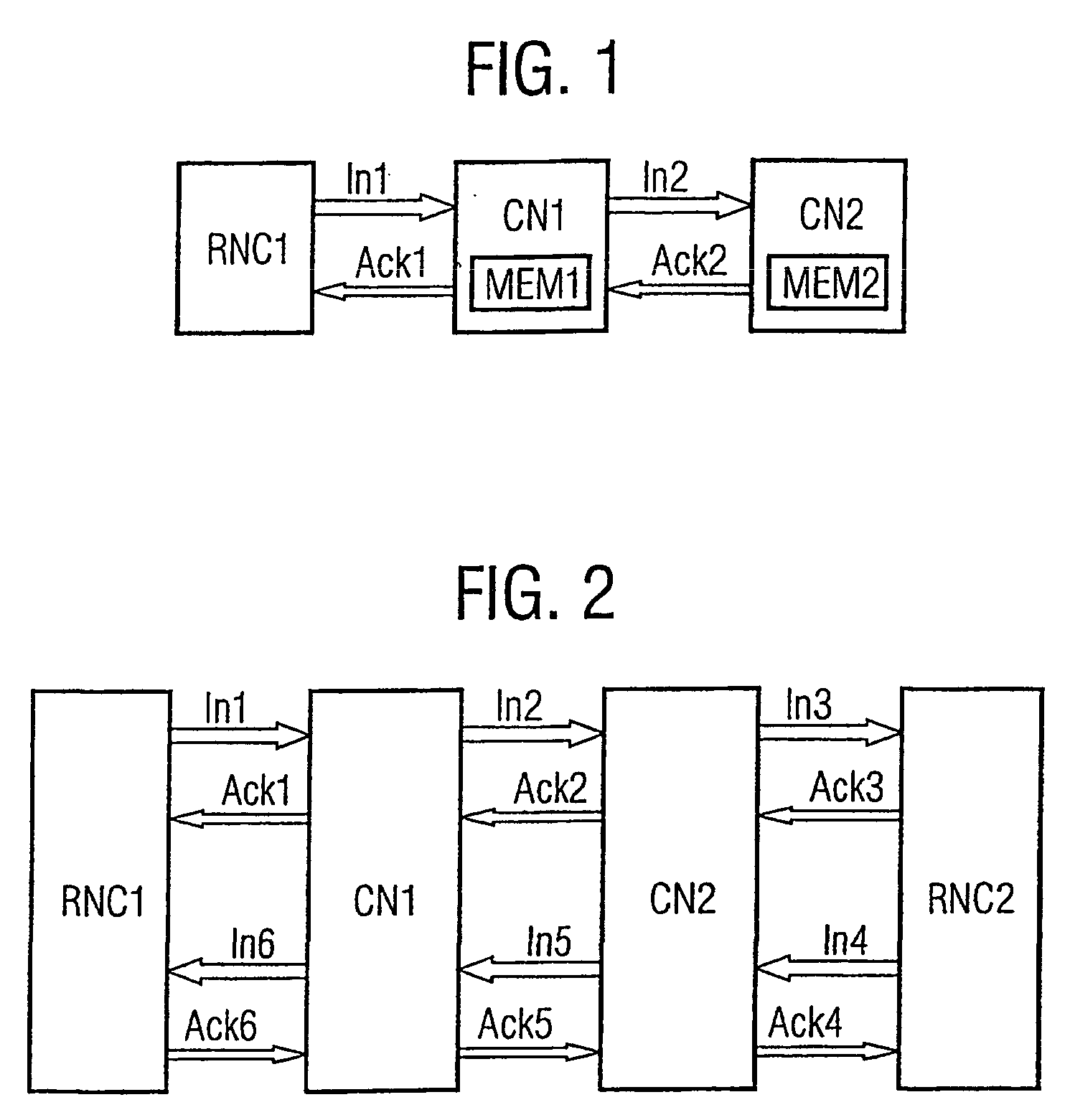
[0019] The proposed method is simple and requires a low processing effort in the nodes because no mapping between different framing protocols is necessary. In a simple implementation, the core network nodes transfer the frames without evaluation of the content. However, every core network node can terminate the framing protocol, establish further connections or connections with different parameters and access the data in the frames using the stored parameters. Especially, the connection can be controlled or adapted in every node with low delay and independent of other nodes in the connection. Because only one protocol is used in a connection, there are no problems of adaptation and a fast evolution of services is possible. A virtual transparent connection between access nodes and a transcoder, respectively between access nodes is possible. Preferably, the described method is performed in a communication network.
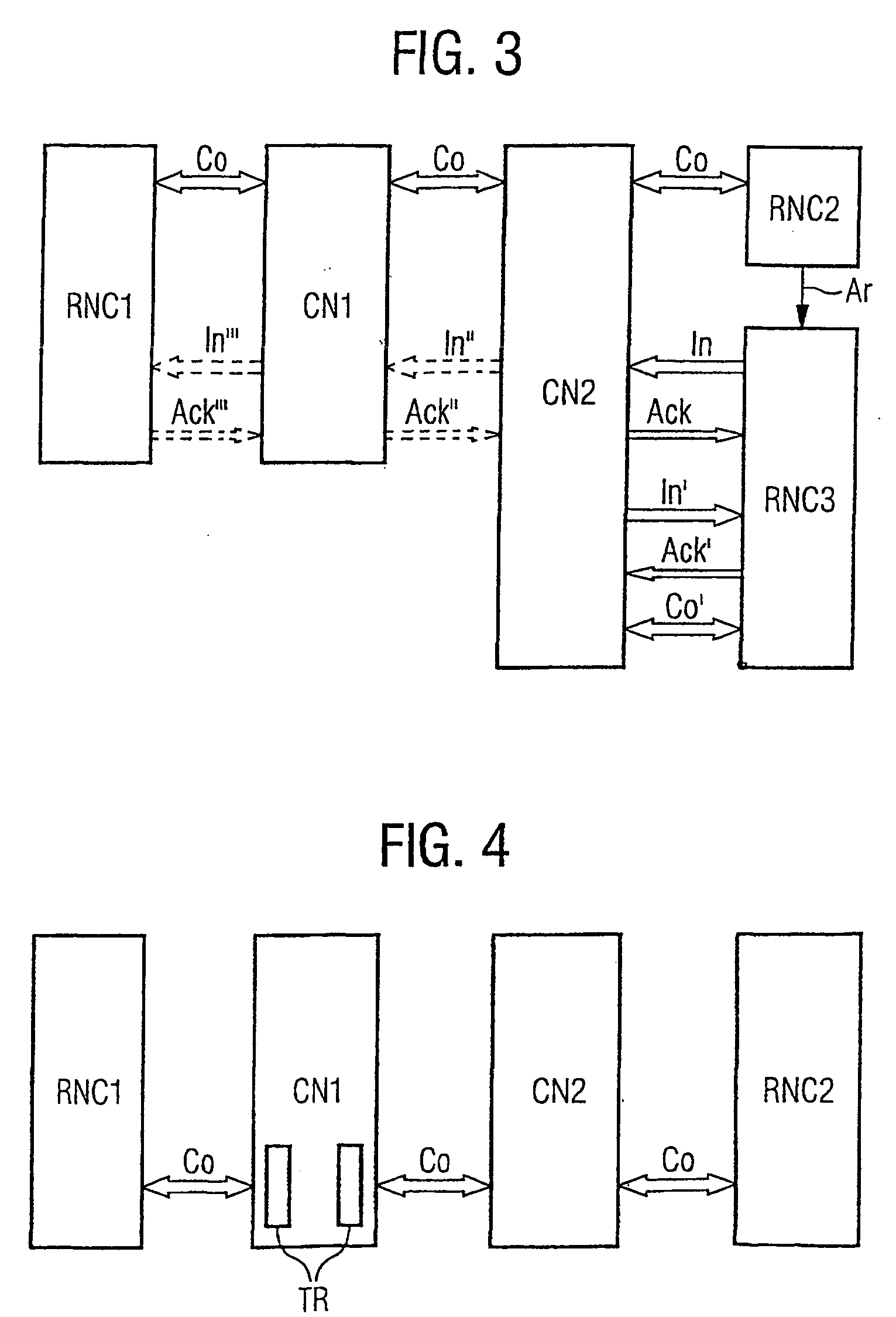
[0023] An advantageous core network node in the connection can insert a function unit into the connection, e.g. break the transcoder free operation of the connection by inserting a transcoder or by inserting a function unit providing a supplementary service. An insertion of supplementary services can occur inside media gateways without an influence on other nodes and links in the connection and is in this way fast and simple to handle.
[0029] If a core network node is adapted to establish connections according to different framing protocols, it preferably checks the framing protocol defined in a request to initialize a connection and selects said framing protocol for the initialization of the connection to a further node. In this way, a mapping between different protocols is avoided while several protocols can be used.

Problems solved by technology

A problem with both RTP and I.366.2 is that they are application dependent and transport layer dependant.
This requires unnecessary overhead to carry the profiles with the payload.
A further problem with SSCS or RTP is that both are service specific.
In this case, it is disadvantageous that there is no control of the user plane.
For example, when a handover is necessary or a supplementary service invocation occurs, the Iu connection has to be cancelled and a new Iu connection must be established which is very inefficient and would degrade the service level.
Although this solution allows establishing an Iu user plane connection transparently through the core network nodes, it has the disadvantage that it requires a high amount of signaling traffic.
In the case, that inband signalling is used, two further problems can occur.
Secondly, an RNC might start initializations without being requested by an MSC, a so-called unsolicited initiation.
As this consumes processor capacity in said core network nodes, this is not always favored.

Method used


Image

  • Method for a connection through a core network
  • Method for a connection through a core network
  • Method for a connection through a core network

Examples


Embodiment Construction

. PREFERRED EMBODIMENTS OF THE INVENTION

[0045] In FIG. 1 the first steps of the initialization of a connection according to the invention is depicted. The connection is established according to the Iu user plane protocol, which is terminated in every core network node CN that may require modifying the user connection, for example for a supplementary service intervention. From a first access node RNCI a message In1 to initialize a connection is sent to a first core network node CN1. In the example, the message In1 is an Iu initialize packet data unit. A processing system of the first core network node CN1 extracts a set of parameters, especially RFCIs, from the message In1 and stores them in a memory MEM1. The first core network node CN1 sends an acknowledgement Ack1 of the message In1 to the first access node RNCI and creates a further message In2 comprising the parameter set. The core network node CN1 can decide to allow transparent Iu UP transmission after call establishment. In t...


PUM


Abstract

In a method for the establishment of a connection between a first node (RNC1) and a second node (RNC2), both are connectable to a core network which comprises interconnected core network nodes (CN1, CN2). The first node (RNC1) signals a call request to a first core network node (CN1). If the first node is an access node, it sends an initialization according to a framing protocol, wherein a set of parameters for the framing of information sent over the interface between the first access node (RNC1) and the first core network node (CN1). If the first node is no access node, a first control server (MSC1) defines said set of parameters. The set of parameters is transmitted to the first core network node (CN1) and the first core network node (CN1) stores the parameter set. The first core network node (CN1) initializes the connection (Co) to a further core network node according to said protocol and the further core network node stores the parameter set. The initialization of the connection (Co) to and the storing of parameters in further core network nodes is performed stepwise until a final core network node (CN2) is reached which is connectable to the second access node (RNC2). The final core network node (CN2) initializes the connection (Co) to the second access node (RNC2) according to said protocol and the second access node (RNC2) stores the parameter set. A core network node and a program unit embodying the invention are also described.

Description

[0001] The present invention relates to a method according to the preamble of claim 1. Devices and software programs embodying the invention are also described.[0002] Communication networks can be subdivided into core networks and access networks, the latter providing access to user equipment, for example a wireless access for mobile user equipment to a radio access network. Core networks interconnect access networks and optionally further networks, e.g. the Internet. In the UMTS architecture, an access network can be controlled by an RNC (radio network controller) which is connected to the core network and provides access to the core network, i.e. serves as access node. In 3GPP (3.sup.rd Generation Partnership Project) Technical Specification 3G TS 25.415 V3.2.0, the interface between the access node and a node in the core network is denoted as Iu interface. Over the Iu interface, connections can be established according to the Iu user plane protocol.[0003] RFCIs (radio access bear...

Claims


Application Information

Patent Timeline
IPC IPC(8): H04W76/02H04W92/22
CPCH04W92/22H04W76/022H04W76/12
Inventor HELLWIG, KARLHODGES, PHILMAUPIN, ALAINISRAELSSON, MARTINNOGUERA, JUAN
Owner TELEFON AB LM ERICSSON (PUBL)
Learn More