Image heating device and image forming apparatus using the same

a heating device and heating device technology, applied in the field of image heating device and image forming apparatus, can solve the problems of alteration or peeling of this elastic layer, and achieve the effects of short warm-up time, small capacity, and rapid heating

Inactive Publication Date: 2004-05-27
PANASONIC CORP
View PDF2 Cites 28 Cited by
  • Summary
  • Abstract
  • Description
  • Claims
  • Application Information

AI Technical Summary

Benefits of technology

[0020] The present invention has been made to overcome the above-mentioned problems of the prior art. It is an object of the present invention to provide an image heating device with a small capacity that can be heated rapidly and an image forming apparatus. It is a further object of the present invention to provide an image forming apparatus including an image heating device requiring a short warm-up time, which can deal with abnormal conditions and thus can be used stably.
[0023] An image heating device according to a second configuration of the present invention includes a rotatable belt having a heat resistance; a heat-generating member, which is at least partially conductive and arranged in contact with an inner peripheral surface of the belt; a fixing roller, the fixing roller and the heat-generating member movably suspending the belt therebetween; and a magnetization means for heating the heat-generating member through magnetization, which is arranged outside the heat-generating member. The image heating device according to the second configuration is characterized in that the magnetization means heats the heat-generating member through magnetization only when a rotating operation of the belt is being performed. The image heating device according to this second configuration exhibits the same effect as that in the image heating device according to the above-mentioned first configuration.
[0034] An image heating device according to a fifth configuration of the present invention includes a magnetization means; and a rotatable conductive heat-generating body to be heated by the magnetization means, with the magnetization means heating the conductive heat-generating body through magnetization after a rotating operation of the conductive heat-generating body is started. The image heating device according to the fifth configuration is characterized in that the conductive heat-generating body is rotated at a first speed when a temperature thereof is less than a predetermined set temperature and at a second speed when a temperature thereof is not less than the predetermined set temperature. This is because the time required for raising temperatures varies depending on rotational speeds. To shorten the time required for raising temperatures, it is important to prevent the heat of heat-generating body from being removed by other members as well as to increase the speed at which the conductive heat-generating body is heated. A typical example of members removing the heat from the conductive heat-generating body is a pressure roller. When the pressure roller is at rest, the pressure roller removes only a small amount of heat from the conductive heat-generating body because it removes heat only from the portion contacting the fixing roller. However, when the pressure roller is rotating, the entire pressure roller removes heat from the conductive heat-generating body. Accordingly, the amount of heat removed by the pressure roller increases in accordance with increase in the rotational speed of the pressure roller. On this account, by rotating the conductive heat-generating body at a low speed when raising the temperature of the conductive heat-generating body and then changing the speed to a normal speed (i.e., the speed at the time of routine operations) when the temperature of the conductive heat-generating body has reached a predetermined temperature, the time required for raising the temperature can be shortened.
[0035] In the case of an image heating device of belt type including a fixing roller and a pressure roller, a more significant effect can be obtained because the fixing roller also removes heat from the conductive heat-generating body.
[0050] In an image heating device of belt type, temperature measurement preferably is performed in a portion between the nip portion and the heat-generating member to reflect the amount of heat removed by fixing. However, if the temperature sensor is pressed against the surface of the belt, which is made thin, the surface of the belt is damaged to reduce the life thereof, thereby causing defective images to be obtained. On this account, it is preferable that the temperature sensor is pressed against the rear surface of the belt. In this case, however, the temperature sensor cannot perform accurate temperature measurement without a pressing member opposing the temperature sensor via the belt, due to vibration or snaking of the belt. Therefore, by providing the temperature sensor on the side of the rear surface of the belt so as to oppose a member pressing the belt on the side of the surface of the belt, e.g., an oil application roller or a cleaning roller, the temperature sensor can perform accurate temperature measurement without damaging the belt. In the image heating devices employing electromagnetic induction heating, rapid heating and subtle temperature control can be performed. In such devices, this configuration is more effective since temperature measurement of the belt thus becomes important.

Problems solved by technology

If the magnetization means heats the heat-generating member through magnetization before the rotating operation of the heat-generating member is started, a temperature of the heat-generating member is only partially made abnormally high, thereby causing alternation of the heat-resistant belt that is in contact with the heat-generating member, as well as permanent set of the belt in accordance with the curvature of the heat-generating member.
Further, if the surface of the belt is coated with an elastic layer made of silicone rubber, for example, a temperature of the belt is only partially made high, thereby causing alternation or peeling of this elastic layer.
In this case, however, since a temperature of the magnetization means is made high, there is a concern about a heat resistance of the magnetization means.

Method used


Image

  • Image heating device and image forming apparatus using the same
  • Image heating device and image forming apparatus using the same
  • Image heating device and image forming apparatus using the same

Examples


first embodiment

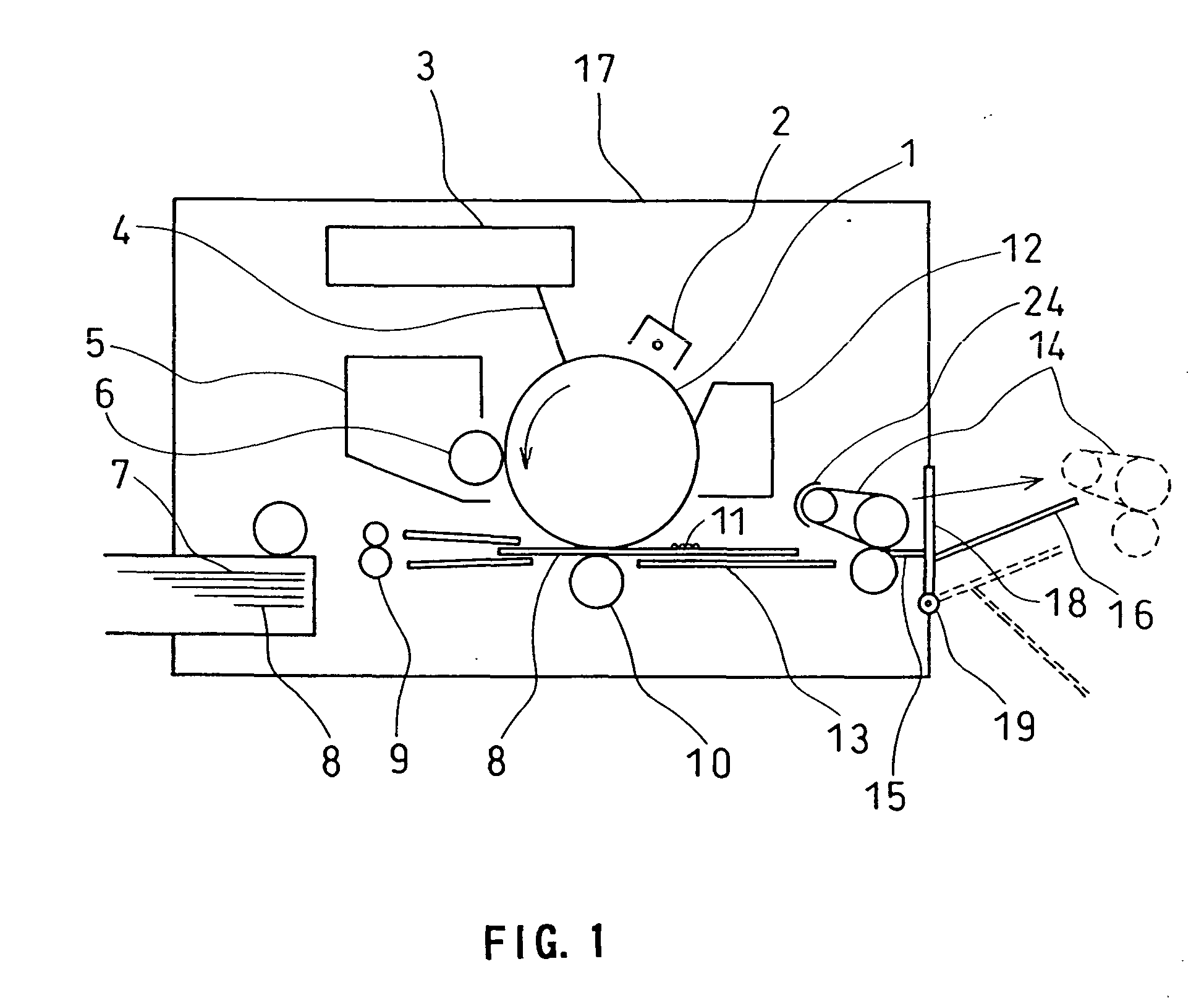
[0101] FIG. 1 is a cross-sectional view showing an image forming apparatus using as the fixing device an image heating device according to the present invention. The configuration and operation of this device will-be described in the following.

[0102] In FIG. 1, reference numeral 17 denotes an outer shell for an image forming apparatus main body and reference numeral 1 denotes an electrophotographic photoreceptor (hereinafter referred to as "photosensitive drum"). While this photosensitive drum 1 is rotationally driven at a predetermined peripheral speed in the arrow direction, its surface is charged homogeneously to a predetermined negative dark potential V0 by a charger 2.

[0103] Reference numeral 3 denotes a laser beam scanner, which outputs a laser beam 4 that is modulated in accordance with a time-series electric digital image signal of image information that is input from a host device (not shown in the drawings) such as an image reading device or a computer. The surface of the ...

example 1

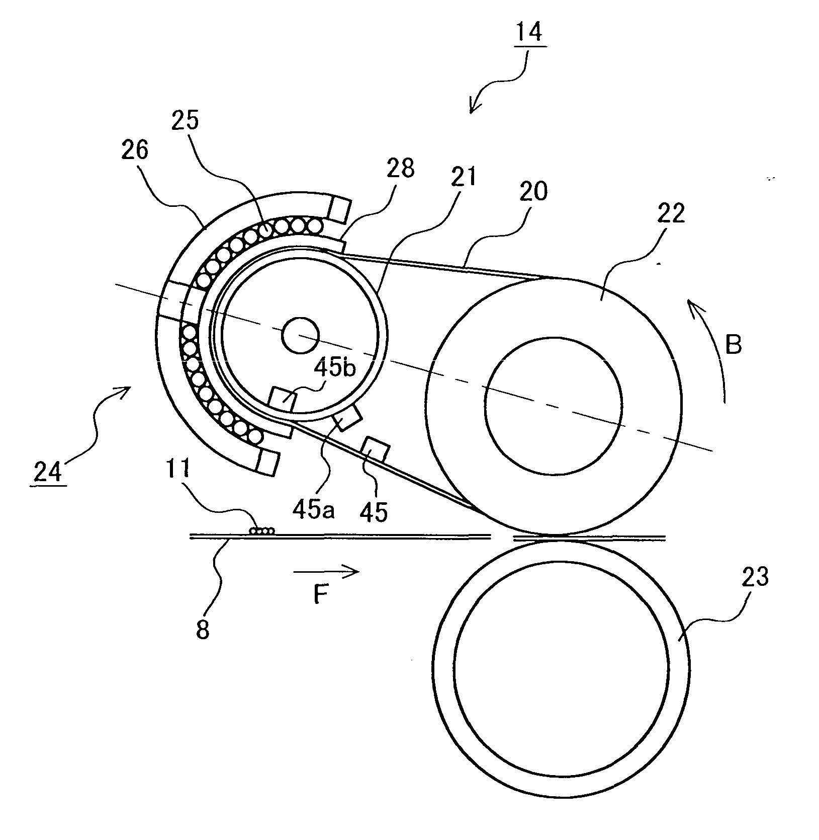
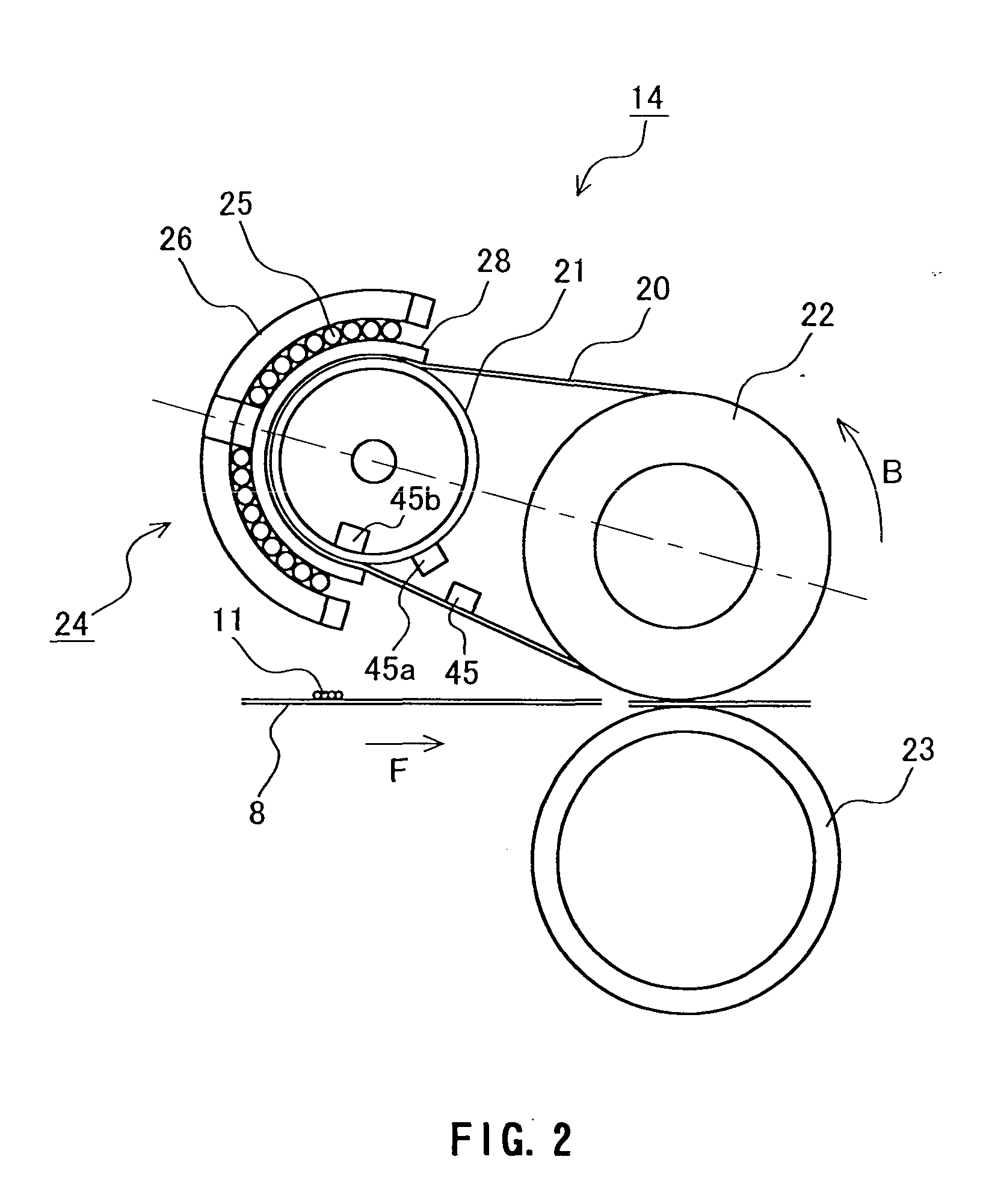
[0109] FIG. 2 is a cross-sectional view showing a fixing device serving as an image heating device in Example 1 of the present invention.

[0110] In FIG. 2, reference numeral 25 denotes a magnetization coil as a magnetization means. This magnetization coil 25 is formed using a litz wire of bundled thin wires. The cross section of the magnetization coil 25 is formed so as to cover a fixing belt 20 looped around the heat-generating roller 21. A core 26 made of ferrite is provided in the center of the magnetization coil 25 as well as in a portion of the rear surface of the magnetization coil 25. For the core 26, a material with high magnetic permeability such as permalloy also can be used in addition to ferrite. The magnetization coil 25 is provided outside the heat-generating roller 21. The heat-generating roller 21 can be heated when a portion of the heat-generating roller 21 is magnetized by the magnetization coil 25. Although the magnetization coil 25 as depicted in FIG. 2 covers and...

example 2

[0129] FIG. 5 is a cross-sectional view showing a fixing device serving as an image heating device in Example 2 of the present invention.

[0130] In this example, elements having the same structure and performing the same function as in the fixing device of Example 1 are referred to with the same numerals and their further explanation has been omitted.

[0131] A fixing belt 50 according to the present example is an endless belt of 60 mm diameter and 90 .mu.m thickness, which comprises a polyimide resin with a glass transition point of 320.degree. C. as a base 51. The surface of the fixing belt 50 is coated with silicone rubber 52 of 200 .mu.m thickness for fixing color images. Also in this example, the heat generation is performed with a heat-generating roller 54. Accordingly, a film-shaped heat-resistant resin such as a fluorocarbon resin can be used for the fixing belt 50.

[0132] The fixing belt 50 is suspended with a predetermined tensile force between a fixing roller 53 of 30 mm diam...


PUM


Abstract

An image heating device with a small thermal capacity that can be heated rapidly. The image heating device includes a fixing belt (20) having a heat resistance; a rotatable heat-generating roller (21), which is at least partially conductive and arranged in contact with an inner peripheral surface of the fixing belt (20); a fixing roller (22), the fixing roller and the heat-generating roller (21) movably suspending the fixing belt (20) therebetween; and a magnetization means (24) for heating the heat-generating roller (21) through magnetization, which is arranged outside the heat-generating roller (21). In this image heating device, the magnetization means (24) heats the heat-generating roller (21) through magnetization after a rotating operation of the heat-generating roller (21) is started.

Description

[0001] The present invention relates to an image heating device permitting reduction of warm-up time and an image forming apparatus. More particularly, the present invention relates to an image heating device for use in image forming apparatus, such as electrophotographical apparatus or electrostatic recording apparatus, that is suitable as a fixing device for fixing unfixed images, and to an image forming apparatus.[0002] Conventionally, as image heating devices, for which fixing devices are a typical example, contact-heating devices such as heat roller type devices and belt type devices, generally have been used.[0003] In recent years, due to the demand for shorter warm-up time and reduced energy consumption, electromagnetic induction heating, by which rapid heating and high efficiency heating are likely to be attained, are attracting great attention (see JP 10(1998)-123861 A).[0004] FIG. 23 shows a cross-sectional view of an image heating device utilizing the electromagnetic indu...

Claims


Application Information

Patent Timeline
Patent Type & Authority Applications(United States)
IPC IPC(8): G03G15/20
CPCG03G15/2064G03G2215/2016G03G15/2028G03G2215/2032G03G15/2025G03G2215/2025
Inventor TATEMATSU, HIDEKIASAKURA, KENJIIMAI, MASARU
Owner PANASONIC CORP
Why Eureka
Try Eureka