Scroll type fluid machine

a fluid machine and scrolling technology, applied in the direction of machines/engines, liquid fuel engines, rotary piston liquid engines, etc., can solve the problems of reducing the efficiency affecting the reliability of the fluid machine, and the difficulty of providing highly accurate machined sliding surfaces to the wrap tip and the flat plate portion, so as to improve the reliability of the scrolling fluid machine, increase the frictional resistance, and reduce the effect of deformation

Inactive Publication Date: 2004-05-27
DAIKIN IND LTD
View PDF5 Cites 23 Cited by
  • Summary
  • Abstract
  • Description
  • Claims
  • Application Information

AI Technical Summary

Benefits of technology

0118] By contrast to the above, in the thirty-first problem solving means both the first flat plate portion (51) and the second flat plate portion (52) are provided in the movable scroll (50), and the inner pressure of the fluid chamber (60) acting on the first flat plate portion (51) and the inner pressure of the fluid chamber (60) acting on the second flat plate portion (52) are cancelled each other. Consequently, even when the inner pressure of the fluid chamber (60) varies, apparently only a pressing force of the present problem solving means acts on the movable scroll (50). Accordingly, in accordance with the present problem solving means inclination of the movable scroll (50) is prevented, just by application of a minimum required pressing force, and it is possible to improve the reliability of the scroll type fluid machine (10) without any increase in frictional resistance during revolutions of the movable scroll (50).
0119] In the thirty-second and thirty-third problem solving means, the fluid chamber (60) is defined also by the low wall portion (57) of the movable side wrap (53) and the planar surface forming portion (49) formed in the stationary side wrap (41). Consequently, in accordance with these problem solving means, the minimum volume of the fluid chamber (60) whose volume varies with the revolution of the movable scroll (50) is made smaller in comparison with a case in which the height of the movable side wrap (53) is held constant. Accordingly, in accordance with these problem solving means it is possible to reduce the number of turns of the stationary side wrap (41) and the number of turns of the movable side wrap (53) while keeping the ratio of the maximum volume and the minimum volume of the fluid chamber (60) constant, and the stationary scroll (40) and the movable scroll (50) are downsized.
0120] In the stationary scroll (40) of each of these problem solving means, the stationary side wrap (41) is shaped like a cantilevered beam extending from the outer peripheral side end toward the central side end and the amount of deformation of its central side portion is likely to become great. By contrast to this, in these problem solving means the planar surface forming portion (49) is formed so as to cross the central side portion of the stationary side wrap (41) the amount of deformation of which is great. Consequently, the rigidity of the central side portion of the stationary side wrap (41) is enhanced by the provision of the planar surface forming portion (49) and its deformation amount is made smaller. This prevents the stationary side wrap (41) from coming into frictional contact with the movable side wrap (53) or the like when deformed. Therefore, the stationary side wrap (41) is prevented from suffering damage. The reliability of the scroll type fluid machine (10) is improved.

Problems solved by technology

If there is created an excessive gap between the wraps which are sliding against each other or between the wrap tip and the flat plate portion which are sliding against each other, this will cause leakage of fluid from the fluid chamber.
As a result, the efficiency of the fluid machine will drop.
However, the problem with conventional scroll type fluid machines is that it is difficult to provide highly accurately machined sliding surfaces to the wrap tip and the flat plate portion.
Accordingly, high accuracy machining of the sliding surface of the flat plate portion with respect to the wrap tip is difficult to carry out.
In other words, it is difficult to reduce the surface roughness of the sliding surface and it is also difficult to improve the flatness of the sliding surface.
Consequently, in conventional scroll type fluid machines it is impossible to effectively control leakage of fluid through a gap between the wrap tip and the flat plate portion.
Due to this, it is difficult to achieve improvements in efficiency.

Method used


Image

  • Scroll type fluid machine
  • Scroll type fluid machine
  • Scroll type fluid machine

Examples


embodiment 1 of invention

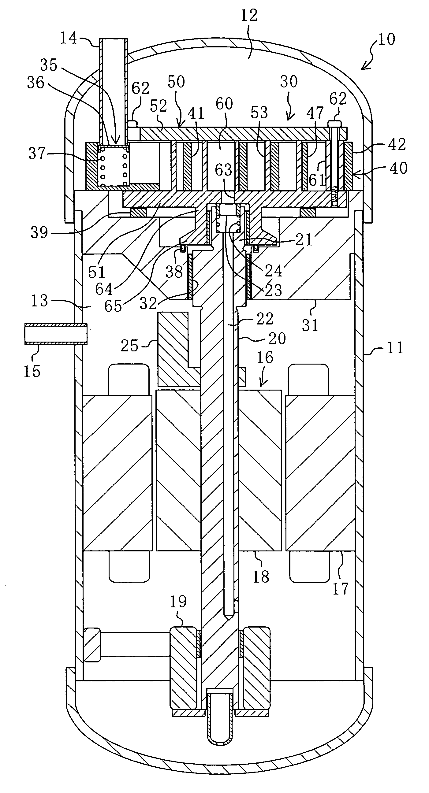
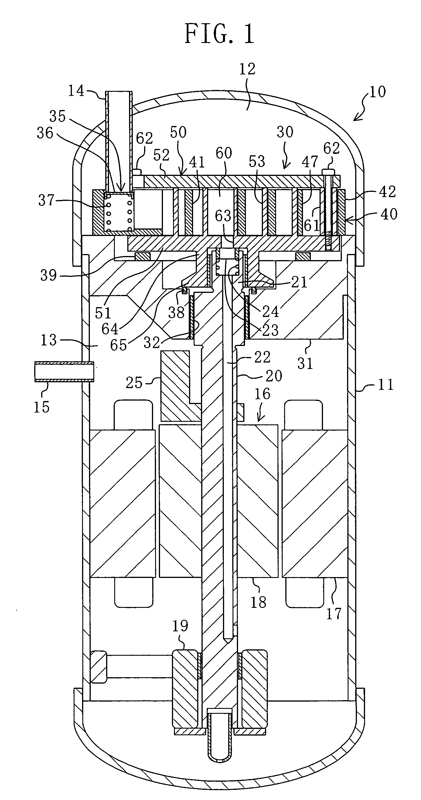
[0149] A first embodiment of the present invention is a scroll compressor (10) composed of a scroll type fluid machine according to the present invention. This scroll compressor (10) is provided in a refrigerant circuit of a refrigerating apparatus.

[0150] As shown in FIG. 1, the scroll compressor (10) has a so-called hermetically sealed construction. This scroll type compressor has a casing (11) which is shaped like a longitudinal, cylindrical, hermetically sealed container. A compression mechanism (30), an electric motor (16), and a lower bearing (19) are disposed in that order (from top down) in the inside of the casing (11). Additionally, a vertically-extending driving shaft (20) serving as a rotary shaft is disposed in the inside of the casing (11).

[0151] The interior of the casing (11) is divided vertically by a housing (31) of the compression mechanism (30). In the inside of the casing (11), a space above the housing (31) becomes a low pressure chamber (12) and a space below t...

fourth modification example

[0234] Fourth Modification Example of First Embodiment

[0235] In the scroll compressor (10) of the foregoing embodiment, in the stationary scroll (40) the height of the outer peripheral portion (42) is equal to that of the stationary side wrap (41). However, instead of employing such an arrangement the following arrangement may be used.

[0236] In other words, the height of the outer peripheral portion (42) may be made somewhat greater than the height of the stationary side wrap (41) (see FIG. 14). In the present modification example, the second flat plate (52) comes into sliding contact with the upper surface of the outer peripheral portion (42) even when the movable scroll (50) is positioned at the downmost position, thereby ensuring that a clearance is always secured between the upper tip of the stationary side wrap (41) and the second flat plate (52).

[0237] Consequently, the tip of the stationary side wrap (41) is prevented from suffering damage from forceful frictional contact wit...

fifth modification example

[0240] Fifth Modification Example of First Embodiment

[0241] In the scroll compressor (10) of the foregoing embodiment, the height of the stationary side wrap (41) is constant in the stationary scroll (40). However, instead of such an arrangement the following arrangement may be employed.

[0242] To sum up, as shown in FIG. 15, the height of the stationary side wrap (41) may become gradually smaller toward the center side from the outer peripheral side of the stationary side wrap (41). In the present modification example, the upper tip surface of the stationary side wrap (41) is an inclined plane inclining downwardly toward the center side from the outer peripheral side of the stationary side wrap (41). On the other hand, the lower tip surface of the stationary side wrap (41) is an inclined plane inclining upwardly toward the center side from the outer peripheral side of the stationary side wrap (41). In addition, it may be arranged such that only the upper tip surface is inclined and ...


PUM


Abstract

A stationary scroll (40) is provided with a stationary side wrap (41) and an outer peripheral portion (42). The stationary side wrap (41) is formed into a spiral wall shape. The outer peripheral portion (42) is formed into a ring-like shape enclosing the periphery of the stationary side wrap (41). The movable scroll (50) is provided with a first flat plate (51), a movable side wrap (53), and a second flat plate (52). The movable side wrap (53) is formed into a spiral wall shape. Additionally, the movable side wrap (53) is caught between the first flat plate (51) and the second flat plate (52), with the movable side wrap (53) in mating engagement with the stationary side wrap (41). In the movable side wrap (53), the first flat plate (51) is formed integrally with the movable side wrap (53). Additionally, the second flat plate portion (52) is formed as a separate body from the first flat plate (51) and the movable side wrap (53) and is coupled to the first flat plate (51) with a bolt (62).

Description

[0001] The present invention relates to fluid machines of the scroll type.[0002] Scroll type fluid machines have been well known in the prior art. For example, Japanese Patent Kokai number (1994)330864 discloses a compressor composed of a scroll type fluid machine.[0003] An arrangement of a typical scroll type fluid machine will be described below. This type of fluid machine includes a stationary scroll and a movable scroll. The stationary and movable scrolls include respective tabular flat plate portions and spiral wraps. In both the scrolls, the wraps are vertically arranged on front surface sides of the flat plate portions. Additionally, in both the scrolls the wraps are formed integrally with the flat plate portions, respectively. The stationary and movable scrolls are disposed in such an orientation that they face each other, and their respective wraps are matingly engaged with each other. The wraps, which are being engaged with each other, are sandwiched between the flat plate...

Claims


Application Information

Patent Timeline
Patent Type & Authority Applications(United States)
IPC IPC(8): F01C1/02F01C17/06F04C18/02F04C23/00F04C28/16
CPCF01C17/06F04C18/0215F04C28/16F04C23/008F04C18/0269F04C18/02
Inventor SHIBAMOTO, YOSHITAKAKATO, KATSUMI
Owner DAIKIN IND LTD
Why Eureka
Try Eureka