Method and apparatus for overlay control using multiple targets

a technology of overlay control and target, applied in the direction of photomechanical equipment, semiconductor/solid-state device testing/measurement, instruments, etc., can solve the problems of inability to optimize the control of critical processing parameters, many of the processing tools currently commercially available suffer certain deficiencies, and tools often lack advanced process data monitoring capabilities

Inactive Publication Date:
View PDF8 Cites 37 Cited by
  • Summary
  • Abstract
  • Description
  • Claims
  • Application Information

AI Technical Summary

Problems solved by technology

However, despite the advances made in this area, many of the processing tools that are currently commercially available suffer certain deficiencies.
In particular, such tools often lack advanced process data monitoring capabilities, such as the ability to provide historical parametric data in a user-friendly format, as well as event logging, real-time graphical display of both current processing parameters and the processing parameters of the entire run, and remote, i.e., local site and worldwide, monitoring.
These deficiencies can engender non-optimal control of critical processing parameters, such as throughput, accuracy, stability and repeatability, processing temperatures, mechanical tool parameters, and the like.
However, because a particular wafer may be processed by different photolithography tools throughout the fabrication cycle, and also because the photolithography tool settings are being constantly updated to control overlay error, the degree of misregistration typically varies between layers.
If the overlay error is sufficiently large, the fabricated device may be defective, have reduced performance, or may require rework.

Method used


Image

  • Method and apparatus for overlay control using multiple targets
  • Method and apparatus for overlay control using multiple targets
  • Method and apparatus for overlay control using multiple targets

Examples


Embodiment Construction

[0028] Illustrative embodiments of the invention are described below. In the interest of clarity, not all features of an actual implementation are described in this specification. It will of course be appreciated that in the development of any such actual embodiment, numerous implementation-specific decisions must be made to achieve the developers' specific goals, such as compliance with system-related and business-related constraints, which will vary from one implementation to another. Moreover, it will be appreciated that such a development effort might be complex and time-consuming, but would nevertheless be a routine undertaking for those of ordinary skill in the art having the benefit of this disclosure.

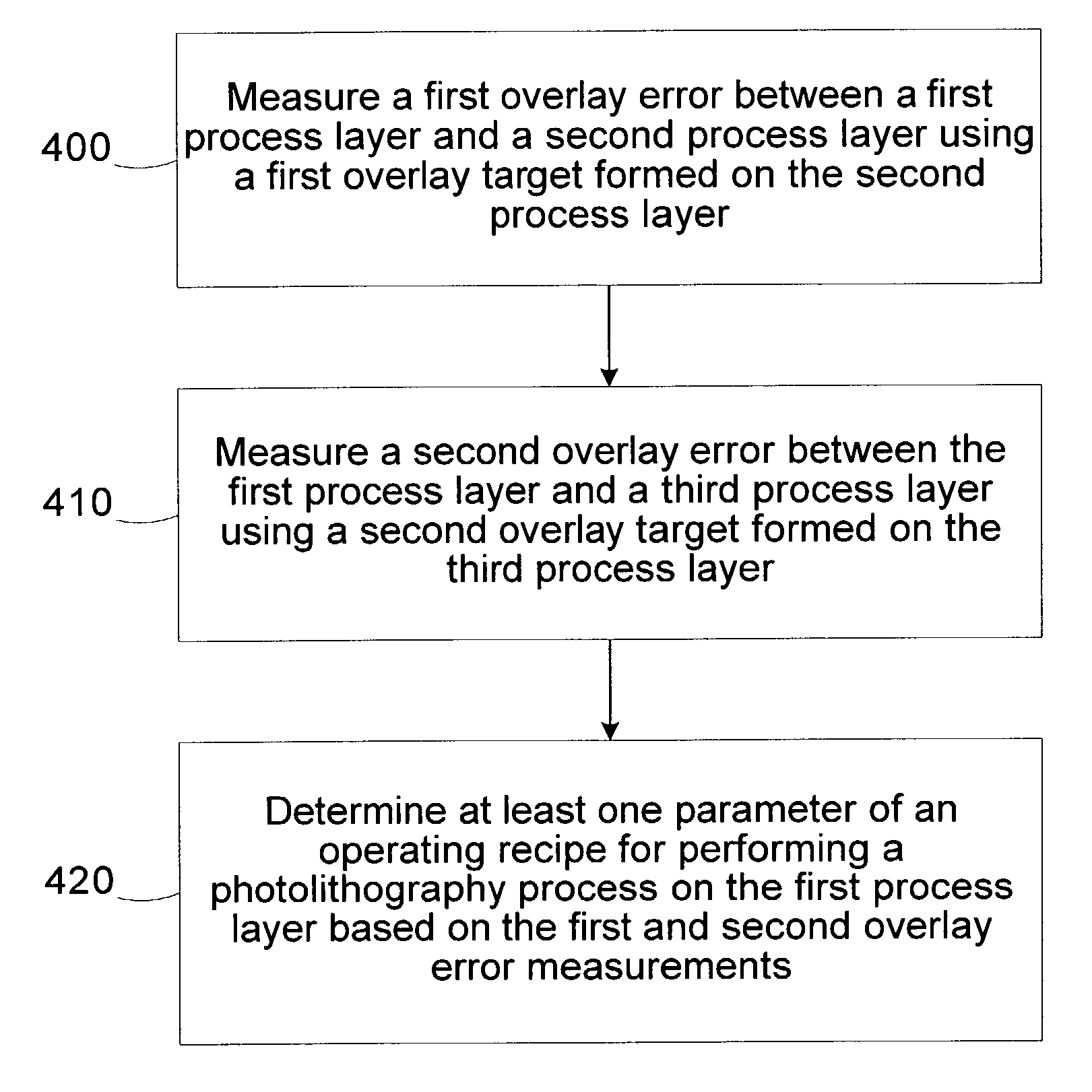
[0029] Overlay control is an important aspect of semiconductor manufacturing. In particular, overlay control involves measuring misalignment errors between semiconductor layers during manufacturing processes. Improvements in overlay control may result in substantial enhancements...


PUM

PropertyMeasurementUnit
distanceaaaaaaaaaa
distanceaaaaaaaaaa
distanceaaaaaaaaaa

Abstract

A method includes measuring a first overlay error between a first process layer and a second process layer using a first overlay target formed on the second process layer. A second overlay error between the first process layer and a third process layer is measured using a second overlay target formed on the third process layer. At least one parameter of an operating recipe for performing a photolithography process on the first process layer is determined based on the first and second overlay error measurements. A system includes a metrology tool and a controller. The metrology tool is configured to measure a first overlay error between a first process layer and a second process layer using a first overlay target formed on the second process layer and measure a second overlay error between the first process layer and a third process layer using a second overlay target formed on the third process layer. The controller is configured to determine at least one parameter of an operating recipe for performing a photolithography process on the first process layer based on the first and second overlay error measurements.

Description

[0001] 1. Field of the Invention[0002] This invention relates generally to the field of semiconductor device manufacturing and, more particularly, to a method and apparatus for overlay control using multiple targets.[0003] 2. Description of the Related Art[0004] There is a constant drive within the semiconductor industry to increase the quality, reliability and throughput of integrated circuit devices, e.g., microprocessors, memory devices, and the like. This drive is fueled by consumer demands for higher quality computers and electronic devices that operate more reliably. These demands have resulted in a continual improvement in the manufacture of semiconductor devices, e.g., transistors, as well as in the manufacture of integrated circuit devices incorporating such transistors. Additionally, reducing the defects in the manufacture of the components of a typical transistor also lowers the overall cost per transistor as well as the cost of integrated circuit devices incorporating su...

Claims


Application Information

Patent Timeline
Patent Type & Authority Applications(United States)
IPC IPC(8): G03F7/20H01L21/66
CPCH01L22/20G03F7/70633
Inventor JONES, GARY K.BODE, CHRISTOPHER A.EDWARDS, RICHARD D.
Why Eureka
Try Eureka