Vehicle air conditioner
- Summary
- Abstract
- Description
- Claims
- Application Information
AI Technical Summary
Benefits of technology
Problems solved by technology
Method used
Image
Examples
first embodiment
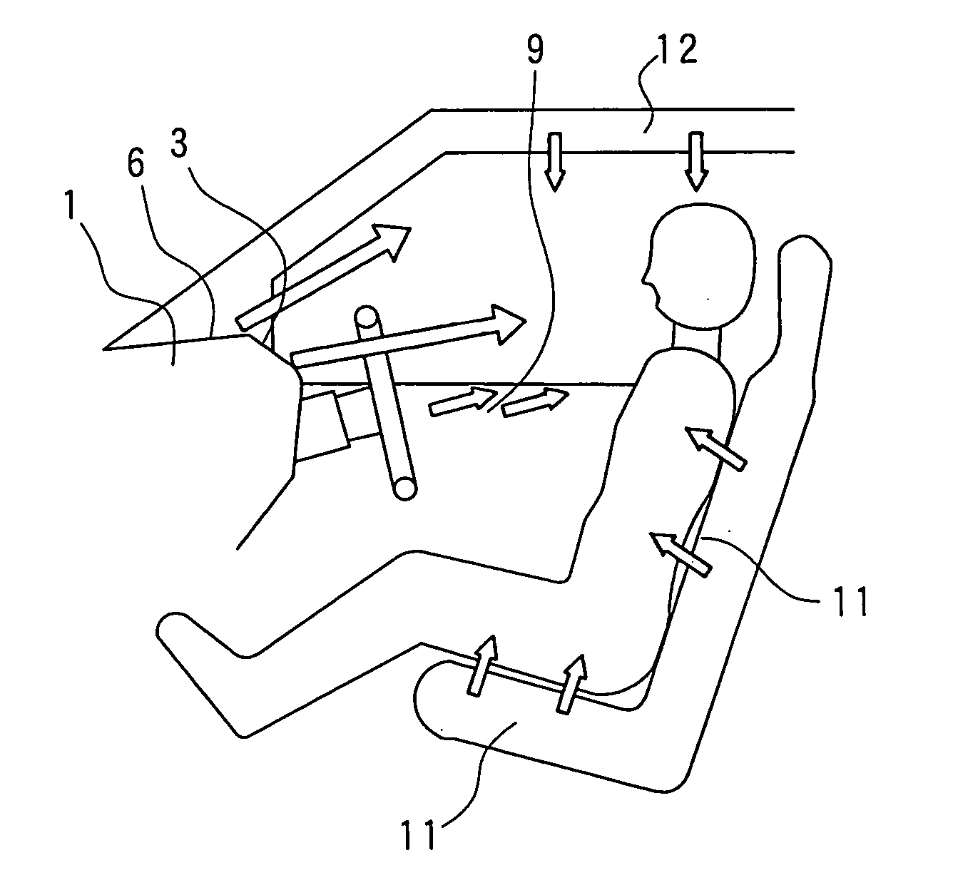
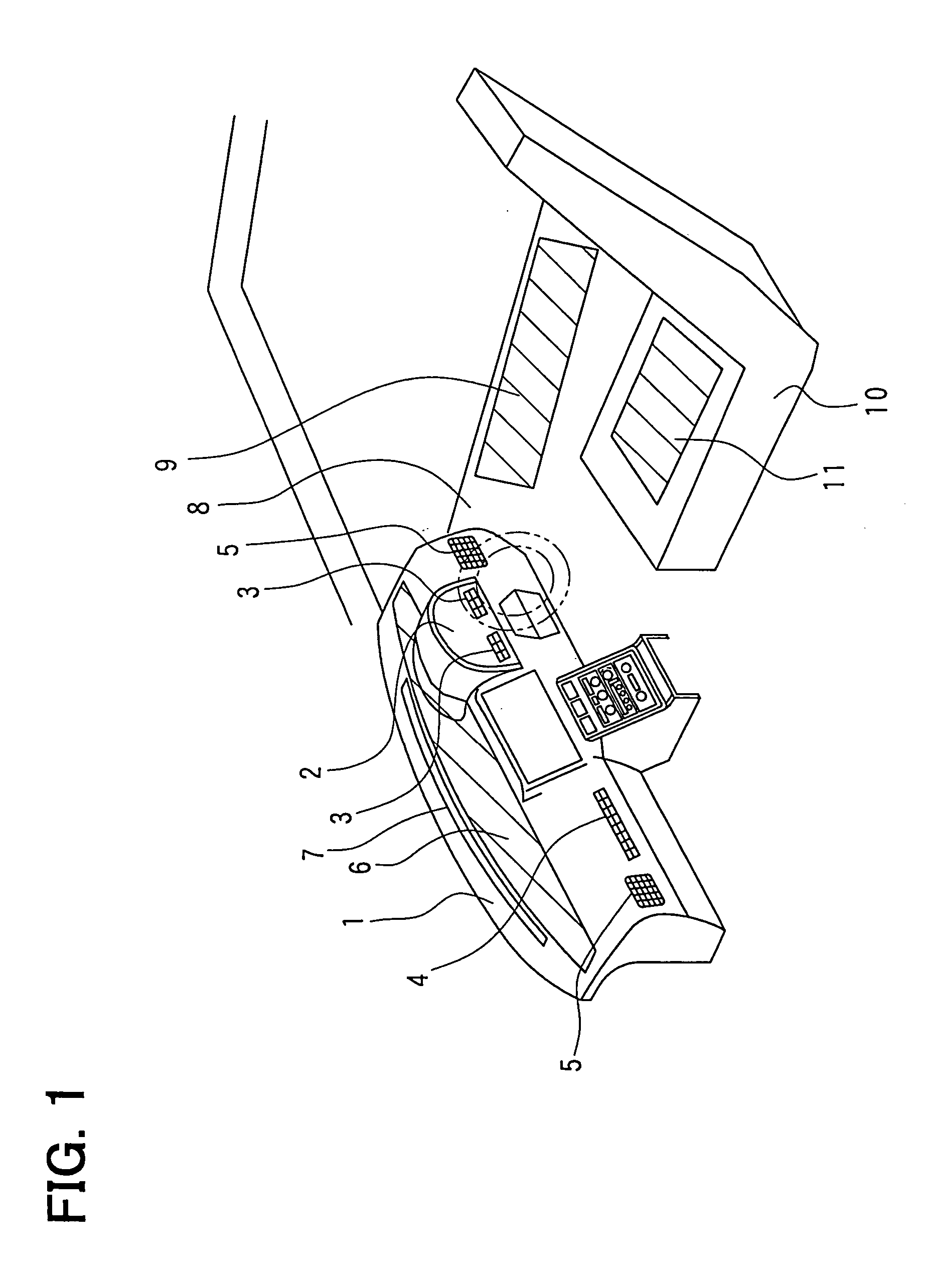
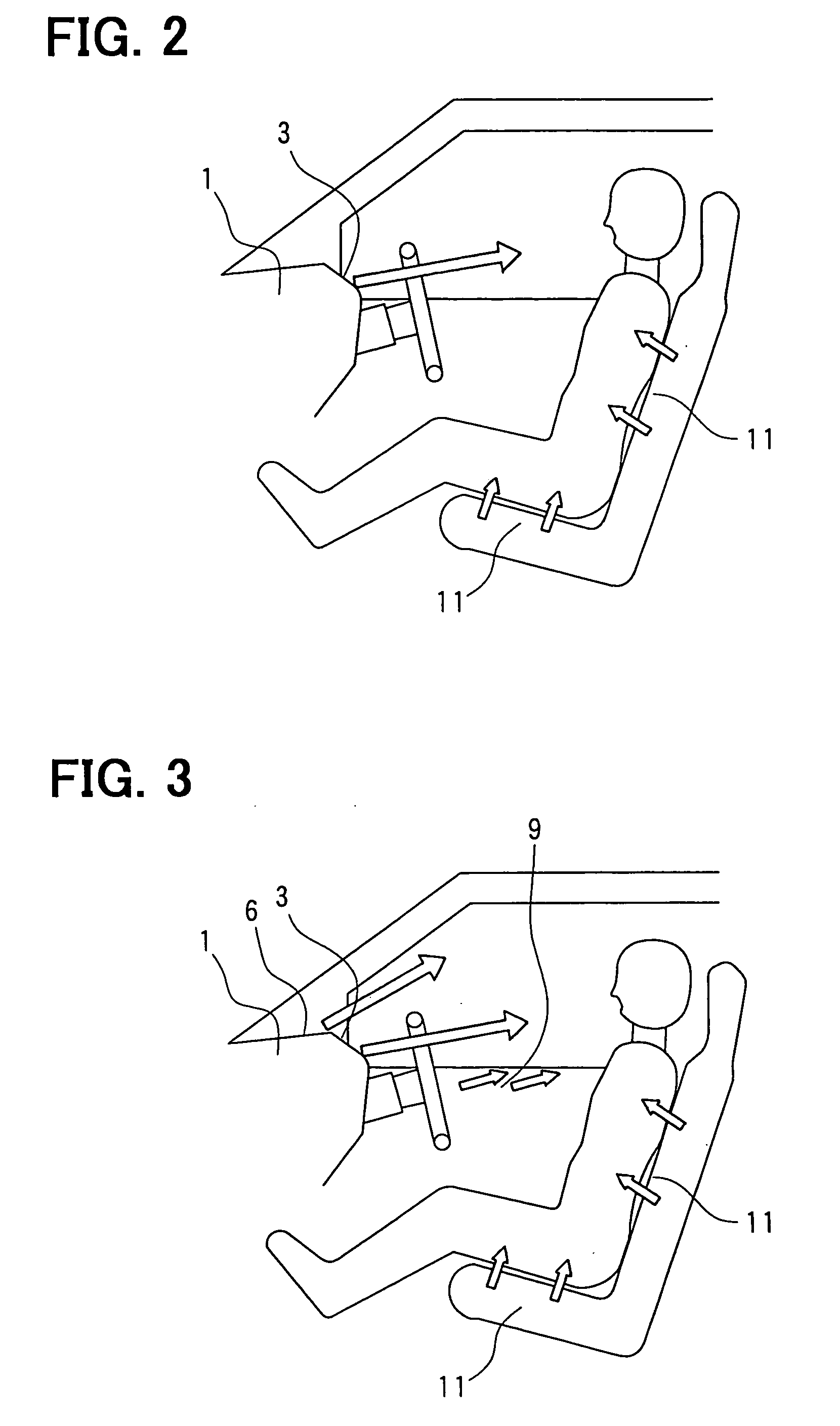
[0028] A vehicle air conditioner according to the first embodiment will be described with reference to FIGS. 1-5. As shown in FIG. 1, an instrument panel portion 2 having a meter member such as a speed meter is provided in a dashboard 1 extending in a vehicle width direction (vehicle right-left direction), at a driver's seat side. An air conditioning unit (not shown), for controlling a temperature and a humidity of air to be blown into a passenger compartment, is provided in the dashboard 1 at a front passenger's seat side next to the driver's seat in the vehicle width direction.
[0029] The air conditioning unit is a general air conditioning unit including a cooling heat exchanger such as an evaporator for cooling air, a heating heat exchanger such as a heater core for heating air after passing through the cooling heat exchanger, a temperature adjustment unit for adjusting an air heating amount in the heating heat exchanger so that conditioned air having a predetermined temperature i...
second embodiment
[0040] The second embodiment of the present invention will be described with reference to FIGS. 6-8. In the above-described first embodiment of the present invention, the instrument panel air outlet 6 and the door air outlet 9 are used as the indirect air outlet. However, in the second embodiment, a ceiling air outlet 12 shown in FIG. 7 is also provided as the indirect air outlet. In the second embodiment, the other parts air similar to those of the above-described first embodiment.
[0041] A conditioned-air blowing state in the initial stage of the cool down operation is shown in FIG. 6. In the initial stage of the cool down operation, as shown in FIG. 6, conditioned air (cool air) is directly blown from the seat air outlet 11 and the face air outlets such as the meter air outlet 3 and the passenger's seat side face air outlet 4, similarly to that in the above-described first embodiment. The later stage of the cool down operation is shown in FIG. 7. In the later stage of the cool dow...
third embodiment
[0043] In the above-described first embodiment, the face air outlet used as the direct air outlet includes the meter air outlet 3 and the passenger's seat side face air outlet 4. In the third embodiment, the meter face air outlet 3 and the passenger face air outlet 4 are eliminated. Instead of the direct air outlets 3, 4, as shown in FIG. 9, a center face air outlet 13 is provided substantially in a center area of the dashboard 1 in the vehicle width direction, to be used as the direct air outlet. In the third embodiment, the other parts are similar to those of the above-described first embodiment, and advantages described above can be obtained.
PUM
 Abstract
Description
Claims
Application Information
 - R&D
- Intellectual Property
- Life Sciences
- Materials
- Tech Scout
- Unparalleled Data Quality
- Higher Quality Content
- 60% Fewer Hallucinations
Browse by: Latest US Patents, China's latest patents, Technical Efficacy Thesaurus, Application Domain, Technology Topic, Popular Technical Reports.
© 2025 PatSnap. All rights reserved.Legal|Privacy policy|Modern Slavery Act Transparency Statement|Sitemap|About US| Contact US: help@patsnap.com


