Method for the analysis of echelle spectra

Inactive Publication Date: 2004-06-17
LEIBNIZ INSTITUT FUR ANALYTISCHE WISSENSCHAFTEN - ISAS -
View PDF6 Cites 19 Cited by
  • Summary
  • Abstract
  • Description
  • Claims
  • Application Information

AI Technical Summary

Benefits of technology

[0012] It is a particular object of the invention to provide an echelle spectrometer and a method, with which the drift of spectral lines in the exit plane can be easily compensated for.
[0014] It is a further object of the invention to provide an echelle spectrometer and a method, with which the unambiguous relationship between the wavelengths and each point in the exit plane can be determined in a simple and automatized manner.
[0021] The manipulating means for adjusting the manipulating variables can be formed by a piezoelectric element connected to a controlled voltage supply. These piezoelectric elements have a length depending on the supplied voltage. The change thereof can be very well adjusted via the supplied voltage. The absolute values of the lengths generally vary very much, but this does not cause any problem by the present method because the actual position of the spectral line is compared to its reference position and therefore provides a feedback which makes it possible to determine the required change of the length of the piezoelectric element from one measurement to the next.
[0029] This way of passive compensation is simple and causes a good stability of the line distances in the direction of the lateral dispersion.
[0039] The separation of the orders is preferably such that the intensity minima between the orders do not extend beyond more than two detector elements perpendicular to the orders. Thereby a high filling factor can be achieved, i.e. an optimal use of the detector surface. The amount of the picture elements not used for the detection of the spectrum is small. At the same time the minimum between the orders is sufficiently pronounced for the determination of the binning ranges. With a good filling factor the detector can be kept as small as possible, whereby the costs are reduced.
[0050] Preferably the function is stored for each order; for the polynomal function for example in the form of the coefficients of the polynomal function for each order. In a particularly preferred embodiment of the invention a order dependent, secondary function is formed from the corresponding coefficients of the polynomal function of each order and this function is fitted by means of a fitting function. The functions describing the geometric shape of the orders do not abruptly change from one order to the next but continuously. By fitting this group of functions the accuracy with respect to errors due to digitization, noise and others can be further improved. The secondary fitting function again can be formed by a polynomal function. Then the polynomal coefficients of the secondary fitting function can be stored. Thereby the amount of data in the memory for the evaluation of the geometric shape of the orders can be further reduced.

Problems solved by technology

Furthermore, the calculated determination of the curvature of the orders does not take into account drifts or other changes of the line positions in the exit plane due to environmental influences.
The calibration of the spectrum with an absolute relationship between the wavelengths and the intensity values is also very time consuming if carried out manually, as the interesting wavelengths are distributed on a plurality of orders and therefore an exact relationship between the wavelength and a pixel is not always available.
A regular compensation of drift or the like is not provided, as it would require much time.
The use of spectrometers outside such laboratories therefore is either impossible or it requires considerable steps to achieve the stabilizing.
Manual manipulations can cause touching of optical components and contamination or misalignment thereof.
Furthermore such manual manipulation is time consuming and relatively inaccurate.

Method used


Image

  • Method for the analysis of echelle spectra
  • Method for the analysis of echelle spectra
  • Method for the analysis of echelle spectra

Examples


Embodiment Construction

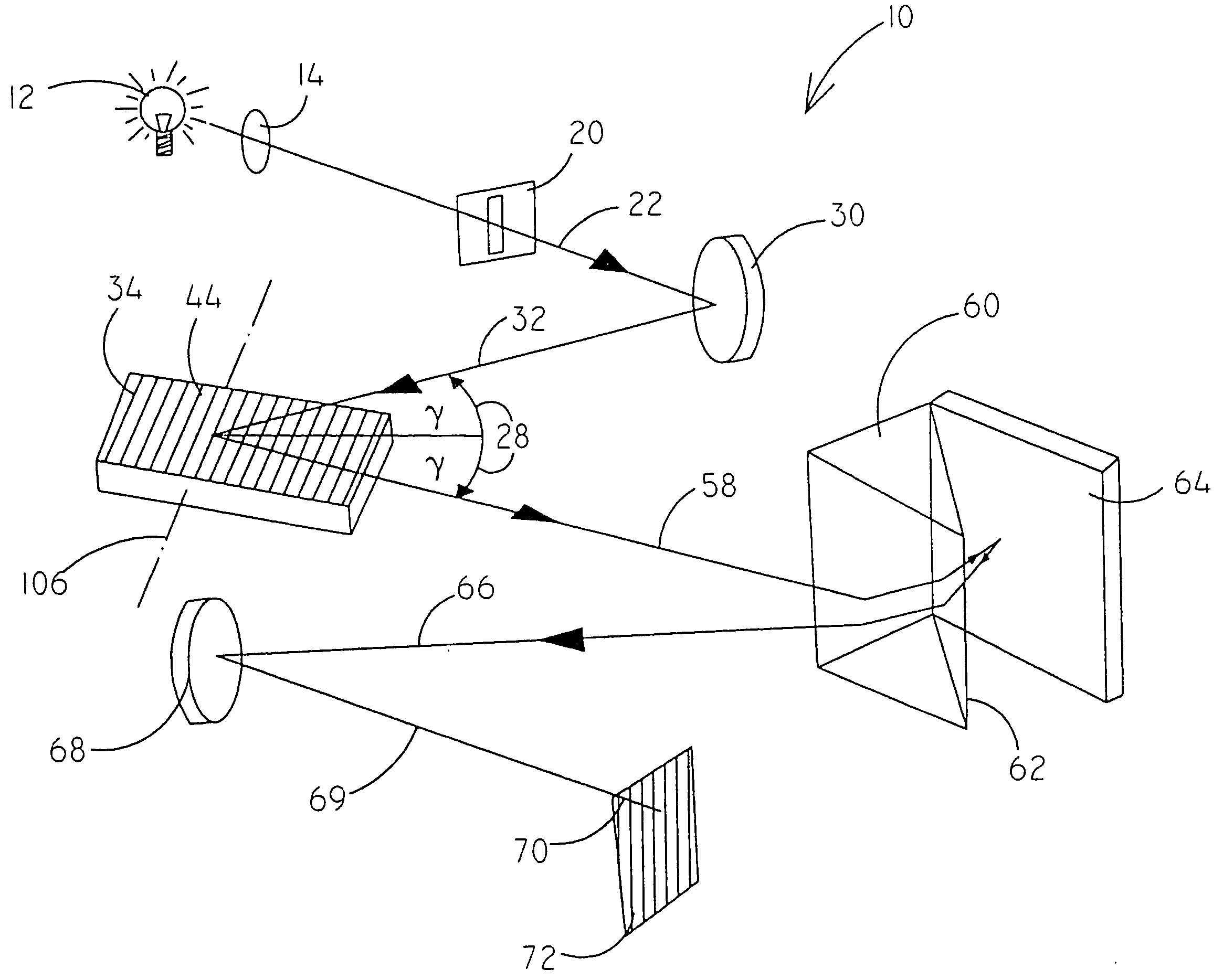
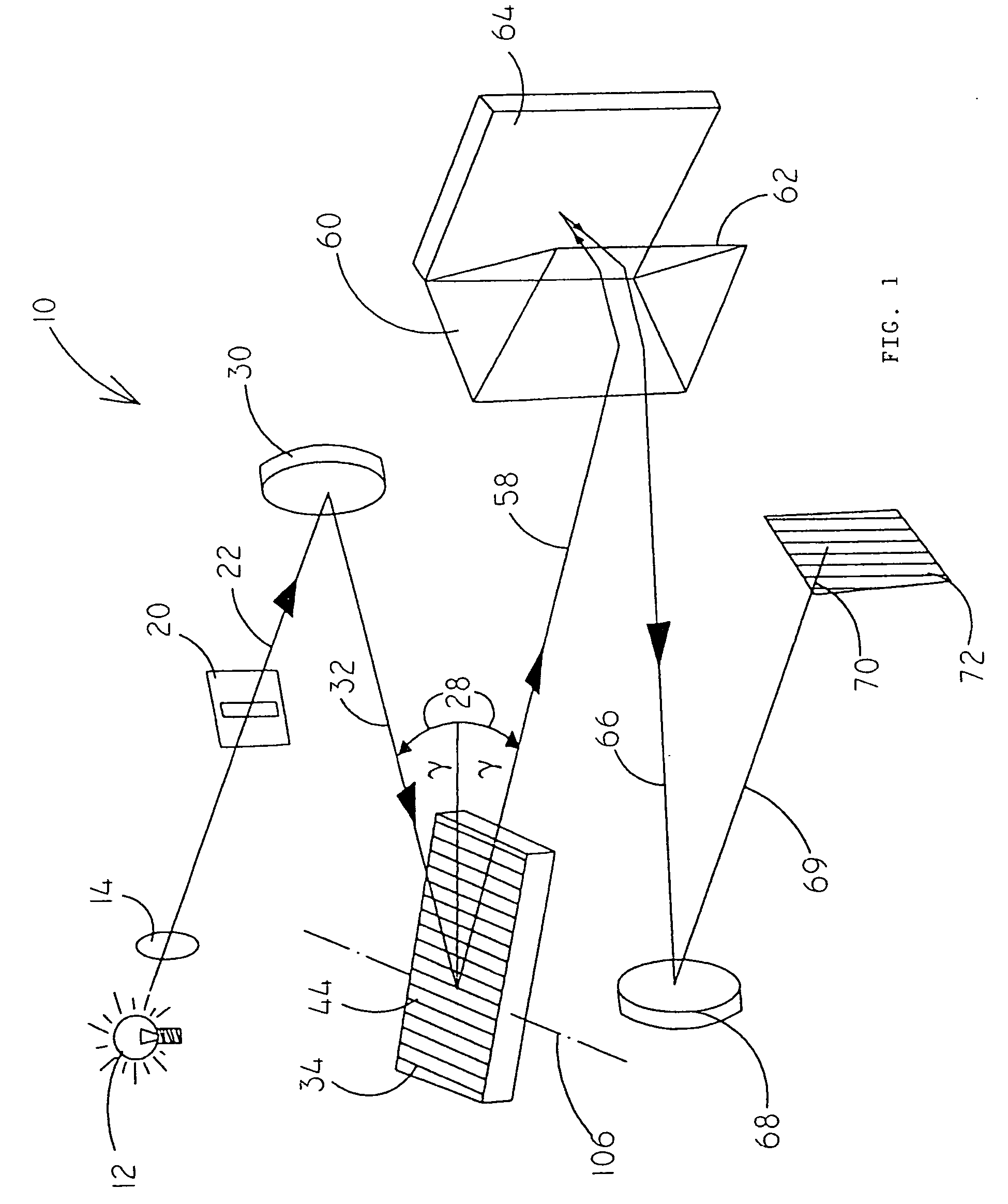
[0095] In FIG. 1 an echelle spectrometer 10 according to the invention is schematically shown. The light of a light source 12 is focused by means of a lens 14 or a mirror onto an entrance slit 20. The optical axis is represented by a line 22 in FIG. 1. The light enters through the entrance slit 20 and is parallelized by means of a spherical concave mirror 30. Then the parallel bundle 32 meets an echelle grating 34 where it is dispersed. The grooves of the grating 44 run in a horizontal direction. The dispersion is perpendicular to the grooves, i.e. in a vertical direction in FIG. 1.

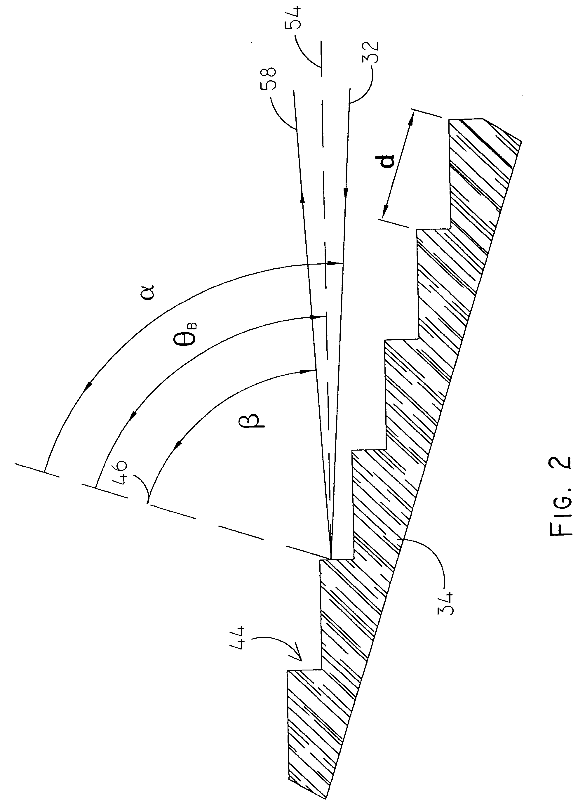
[0096] In FIG. 2 the echelle grating 34 again is shown in greater detail. The distance between the grooves of the grating is denoted d. The angle between the incoming beam 32 and the normal line 46 on the grating is denoted .alpha.. The angle between the diffracted beam 58 and the normal line 46 on the grating is denoted .alpha.. .theta..sub.B denotes the blaze angle of the grooves 44 of the echelle grati...


PUM


Abstract

A method for the wavelength calibration of echelle spectra, in which the wavelengths are distributed across number of orders is characterised by the steps: recording of a line-rich reference spectrum with known wavelengths for a number of the lines, determination of the position of a number of peaks of the reference spectrum in the recorded spectrum, selection of at least two first lines of known order, position and wavelength, determination of a wavelength scale for the order in which the known lines lie, by means of a fit function gammam(x), determination of a provisional wavelength scale gamma?m 1<custom-character file="US20040114139A1-20040617-P00900.TIF" wi="20" he="20" id="custom-character-00001" / >(x) for at least one neighbouring order m 1, by means of addition / subtraction of a wavelength difference gammaFSR which corresponds to a free spectral region, according to gamma<custom-character file="US20040114139A1-20040617-P00900.TIF" wi="20" he="20" id="custom-character-00002" / >m 1 ?(x)=0gammam(x)gammaFSR with gammaFSR=gamma<custom-character file="US20040114139A1-20040617-P00900.TIF" wi="20" he="20" id="custom-character-00003" / >m(x) / m, determination of the wavelengths of lines in said neighbouring order m 1, by means of the provisional wavelength scale gamma 1(x), replacement of the provisional wavelength of at least two lines by the reference wavelength for said lines as obtained in step (a) and repeat of steps (d) to (g) for at least one further neighbouring order.

Description

[0001] The invention relates to an echelle spectrometer according to the first portion of claim 1. Furthermore, the invention relates to a method for compensation of shifts of echelle spectra in the exit plane of an echelle spectrometer.[0002] The invention also relates to an echelle spectrometer according to the first portion of claim 28 and a method for determining binning ranges of a two dimensional plane detector for two dimensional echelle spectra in the exit plane of an echelle spectrometer.[0003] The invention also relates to an echelle spectrometer according to the first portion of claim 47 and a method for wavelength calibration of echelle spectra, wherein the wavelengths are distributed on a plurality of orders.STATE OF THE ART[0004] It is known to generate high resolution spectra by means of echelle spectrometers, wherein the wavelength scale is distributed on a plurality of orders. The orders are separated perpendicular to the dispersion direction of the echelle grating ...

Claims


Application Information

Patent Timeline
IPC IPC(8): G01J3/02G01J3/06G01J3/18G01J3/28
CPCG01J3/02G01J3/0202G01J3/06G01J2003/2866G01J3/28G01J3/2803G01J3/1809
Inventor FLOREK, STEFANOKRUSS, MICHAELBECKER-ROSS, HELMUT
Owner LEIBNIZ INSTITUT FUR ANALYTISCHE WISSENSCHAFTEN - ISAS -
Why Eureka
Try Eureka