Coherent optical detection and signal processing method and system

a signal processing and optical detection technology, applied in electromagnetic transmission, electrical equipment, transmission, etc., can solve the problems of wdm transmission system impairment, vsb format requires extra complexity in the transmitter, and has a worse sensitivity than standard modulation

Active Publication Date: 2004-06-17
HUAWEI TECH CO LTD
View PDF17 Cites 195 Cited by
  • Summary
  • Abstract
  • Description
  • Claims
  • Application Information

AI Technical Summary

Problems solved by technology

This proposal has the advantage that a low bandwidth detector can be used, as for homodyne detection, but it has the disadvantage that the following components need to work at high IF frequencies. K. Yonenaga in "Dispersion compensation for homodyne detection systems using a 10-Gb/s optical PSK-VSB signal" (Yonenaga) discloses compensating for CD after homodyne detection, but disclosed using a vestigial sideband (VSB) modulation format.
However, VSB formats require extra complexity in the transmitter and suffer from the disadvantage of having a worse sensitivity than standard modulation.
Howeve...

Method used


Image

  • Coherent optical detection and signal processing method and system
  • Coherent optical detection and signal processing method and system
  • Coherent optical detection and signal processing method and system

Examples


Embodiment Construction

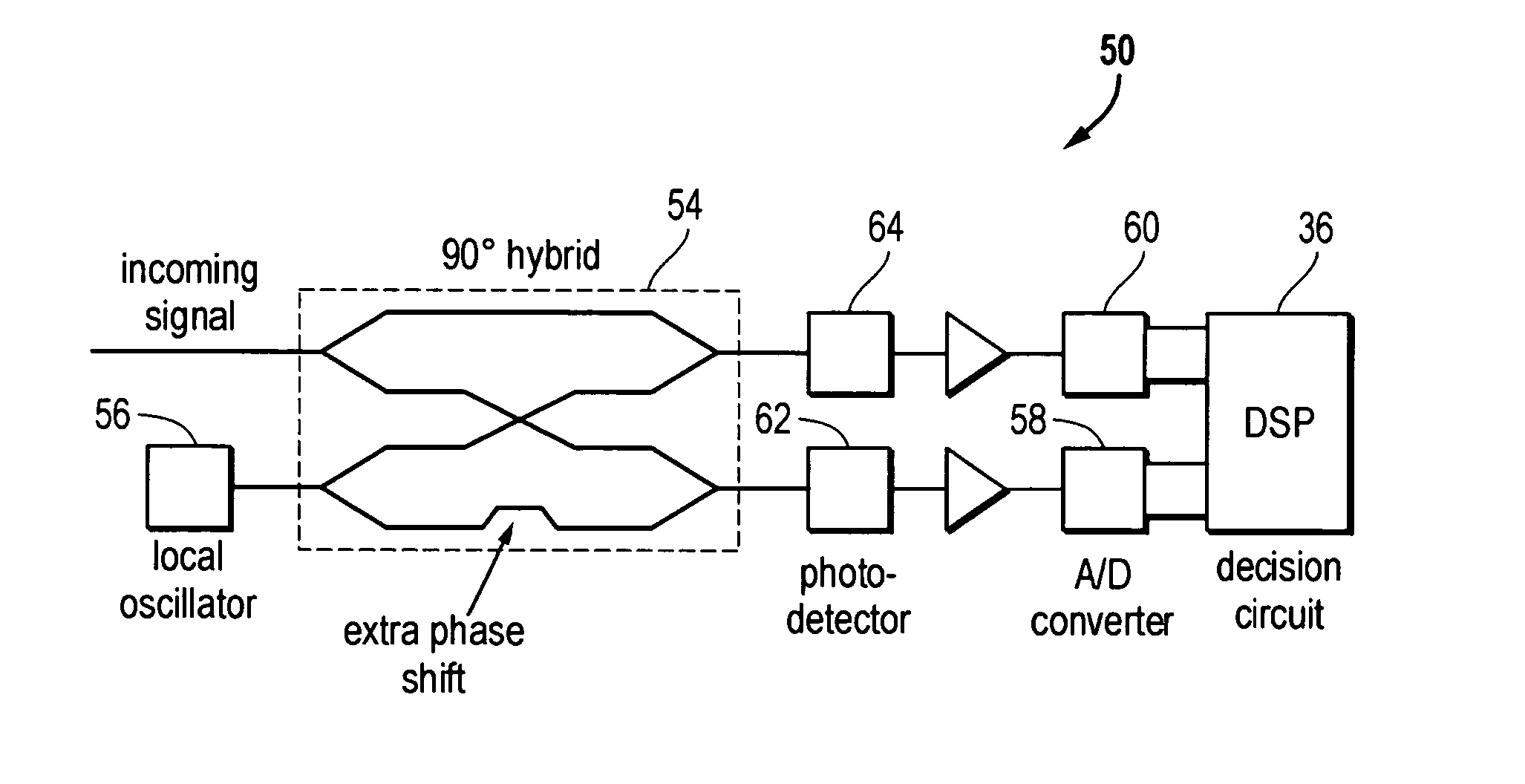
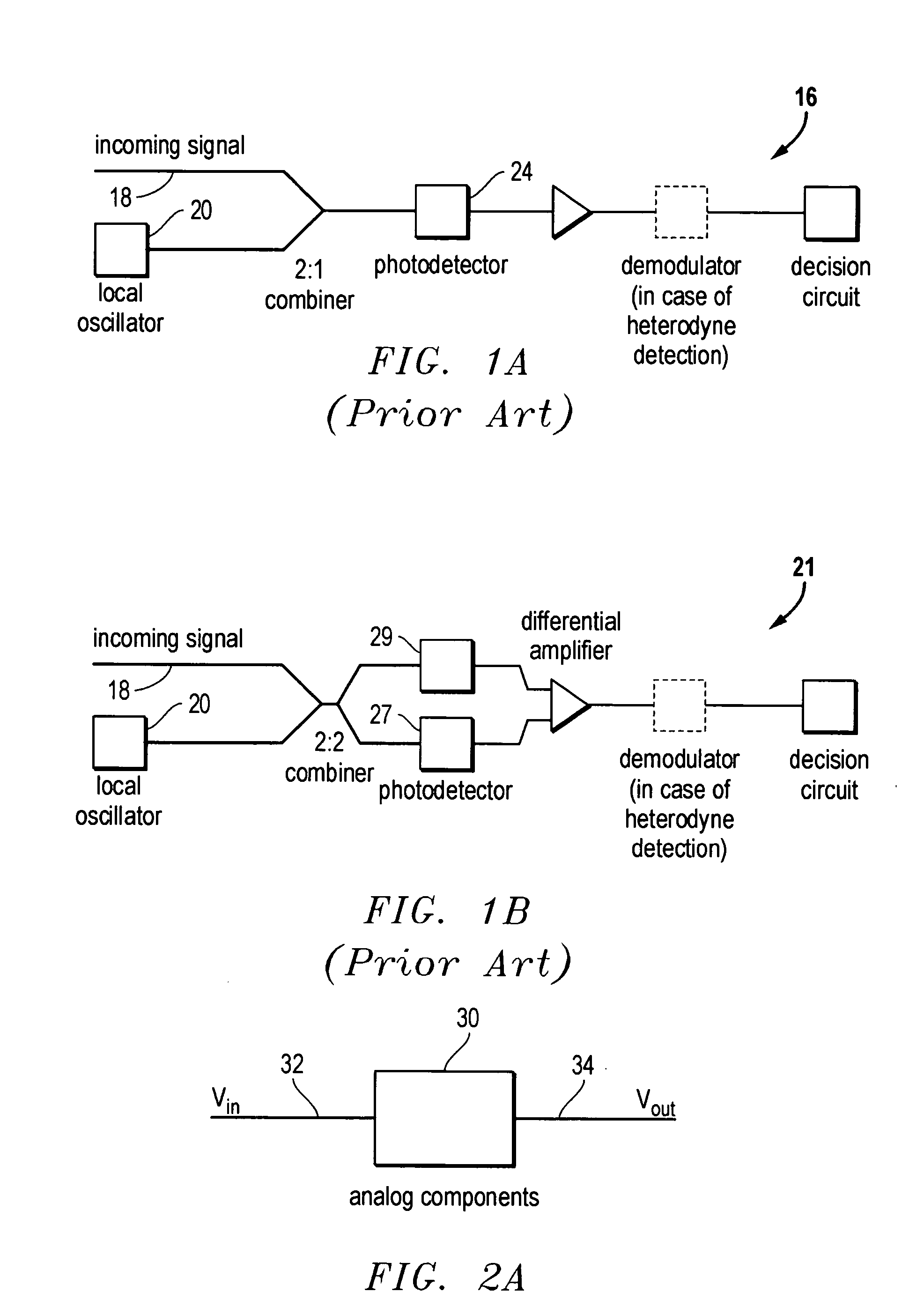
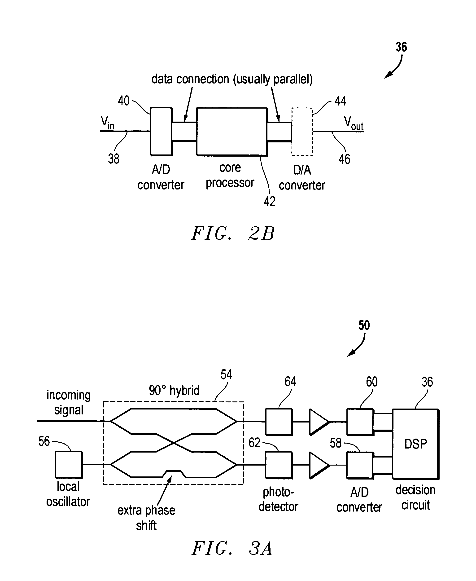
[0047] In the present invention, digital signal processing (DSP) is employed to recover optical signals. Mr. Richard Lyons in "Understanding Digital Signal Processing" discloses the basic principles behind DSP. FIG. 2A is a simplified block diagram illustrating the components of a generic analog signal processor (ASP) 30. A signal processor is a unit, which takes in a signal, typically a voltage vs. time, and performs a predictable transformation on it. This transformation may be described by a mathematical function. The ASP 30 transforms an input signal voltage 32 into an output signal voltage 34. The ASP may utilize capacitors, resistors, inductors, transistors, etc. to accomplish this transformation. FIG. 2B is a simplified block diagram illustrating the components of a generic digital signal processor 36. An input signal 38 is digitized by an analog to digital (A / D) converter 40 that is converted into a sequence of numbers. Each number represents a discrete time sample. A core p...


PUM


Abstract

A method and system of coherent detection of optical signals. The system utilizes a digital signal processor to recover an incoming optical signal. The system employs a local oscillator, which does not need to be phase locked to the signal. The signal may be consistently recovered, even when the polarization state varies over time. Additionally, the signal may be recovered when it comprises two channels of the same wavelength that are polarization multiplexed together. In addition, any impairment to the signal may be reversed or eliminated.

Description

[0001] This utility application claims the priority date of Provisional Patent Application Ser. No. 60 / 432500 by Michael G. Taylor, filed Dec. 11, 2002 and Provisional Patent Application No. 60 / 445,742 by Michael G. Taylor, filed Feb. 7, 2003 and is hereby incorporated by reference.[0002] 1. Field of the Invention[0003] This invention relates to optical transmissions over a fiber optic cable. Specifically, the present invention relates to a system and method of coherent detection of optical signals by utilizing digital signal processing to recover signals.[0004] 2. Description of the Related Art[0005] The use of optical fiber cables for the transmission of information was introduced several years ago. Recently, with the hunger by users for the rapid transmission of large amounts of information, the utility of the transmission of optical signals is particularly evident. [see "optical Communication Systems" by J. Gowar (Gowar) and "Fiber-optic Communication Systems" by G. Agrawal (Agr...

Claims


Application Information

Patent Timeline
IPC IPC(8): H04B10/148
CPCH04B10/61H04B10/614H04B10/64H04B10/6162H04B10/63H04B10/6161
Inventor TAYLOR, MICHAEL GEORGE
Owner HUAWEI TECH CO LTD
Why Eureka
Try Eureka