
Birefringent marking

a technology of birefringent and marking, which is applied in the direction of instruments, polarising elements, transportation and packaging, etc., can solve the problems of requiring additional technical effort and equipment, complicated manufacturing methods, and complicated pattern formation methods

Inactive Publication Date: 2004-07-01
MERCK PATENT GMBH
View PDF9 Cites 17 Cited by
  • Summary
  • Abstract
  • Description
  • Claims
  • Application Information

AI Technical Summary

Benefits of technology

[0005] The inventors of the present invention have found that the above aims can be fulfilled by providing a birefringent marking comprising a liquid crystal (LC) material having discrete regions with different thickness. When this birefringent marking is viewed through a polariser, an image is seen that appears to rotate when the polariser is rotated. In particular striking visible effects can be achieved by providing the birefringent marking onto a reflective layer, like for example a metal layer, and / or by providing an optical phase shift or retardation layer between the birefringent liquid crystal layer and the reflective layer. The LC material can easily be provided e.g. directly onto a reflective substrate, thus a security marking can be prepared in an easy way, without the need of complicated methods or techniques and expensive equipment.
[0014] The present invention relates to a method of incorporating a variable birefringent layer to a reflective section of a document, for example a banknote, such that a non regular pattern is seen when viewed through a linear polariser. The birefringent marking and its method of preparation according to the present invention have several advantages over prior art, such as
[0034] The droplets preferably contain a mixture of the LC material and an organic solvent. The LC mixture can be a solution, dispersion or emulsion of the LC material in the solvent. Preferably a solution is used. Evaporation of the solvent from the applied LC droplets creates different thickness in the final LC layer, thus providing a non-uniform feature which is very difficult to copy. In this way, it is possible to prepare multiple security markings from one sample of LC material by the same method, wherein each marking has a unique pattern, like a fingerprint, which can be easily identified and is difficult to forge.
[0042] Thus, for example a substrate like e.g. a banknote, or selected regions thereof, can be printed or coated with a hologram or reflective metal layer, which is then covered by a birefringent marking as described above. This embodiment is particularly suitable for use as false-proof security threads or holograms on banknotes or documents of value, providing a security marking by which the banknote is easy to authenticate when viewed through a polariser.
[0048] In case the reflective substrate is a holographic layer as described above, the use of an additional phase shift or retardation layer leads to an to improved colour play and to an improved visibility of the holographic image, which is otherwise often difficult to recognize especially in a bright environment.
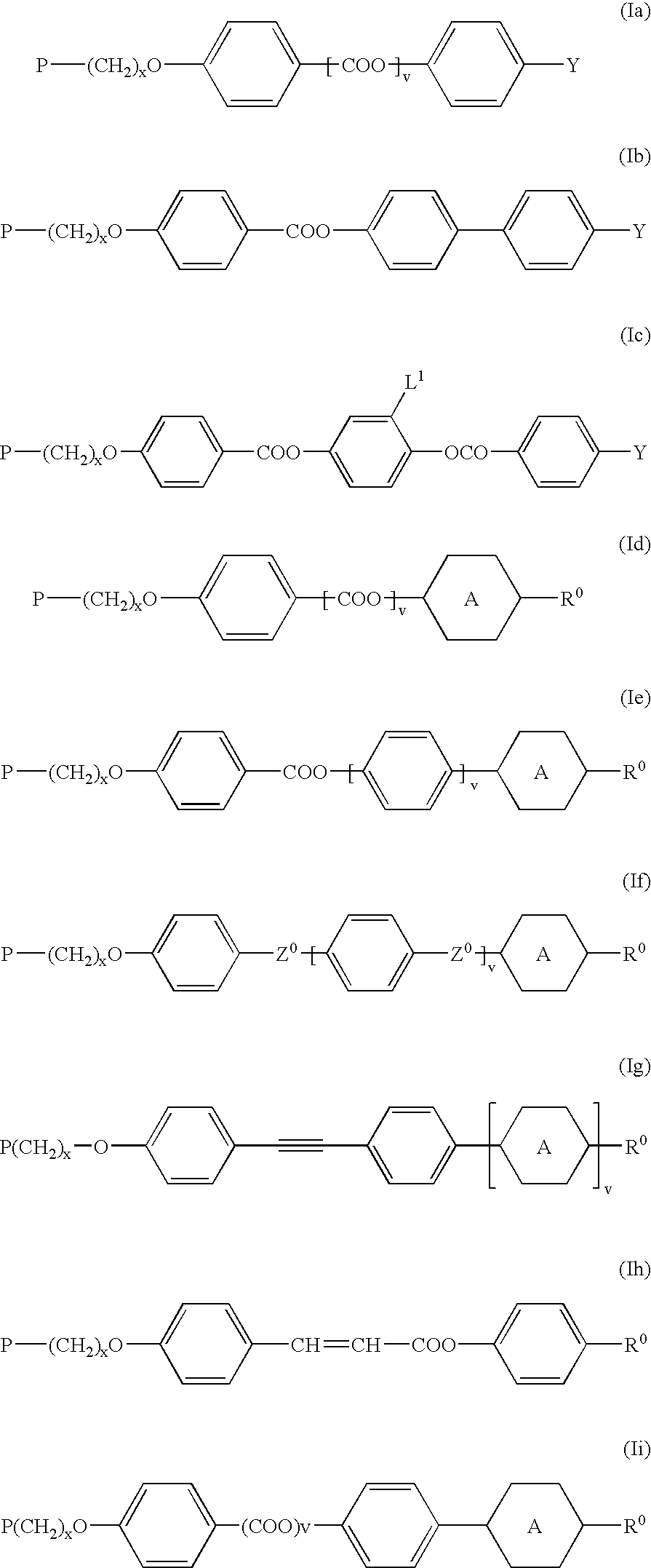
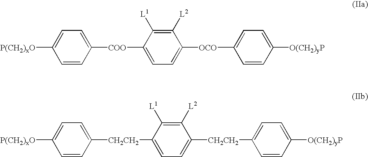
[0057] In another preferred embodiment the polymerisable LC material comprises polymerisable mesogenic compounds having two or more polymerisable functional groups (di- or multireactive or di-or multifunctional compounds). Upon polymerisation of such a mixture a three-dimensional polymer network is formed, which is self-supporting and shows a high mechanical and thermal stability and a low temperature dependence of its physical and optical properties. By varying the concentration of the multifunctional mesogenic or non mesogenic compounds the crosslink density of the polymer film and thereby its physical and chemical properties such as the glass transition temperature, which is also important for the temperature dependence of the optical properties of the polymerised film, the thermal and mechanical stability or the solvent resistance can be tuned easily.

Problems solved by technology

For example, its manufacture is complicated and require a series of manufacturing and processing steps like forming the pattern on the birefringent film, lamination to a high melting point supporting layer and application of the reflective layer.
The methods of forming the pattern are also complicated and require additional technical effort and equipment, like the use of high temperatures or lasers.
Evaporation of the solvent from the applied LC droplets creates different thickness in the final LC layer, thus providing a non-uniform feature which is very difficult to copy.

Method used


Image

  • Birefringent marking
  • Birefringent marking
  • Birefringent marking

Examples


Embodiment Construction

[0079] The following polymerisable mixture is prepared

1 Compound (A) 3.02% compound (B) 7.60% compound (C) 5.70% compound (D) 7.04% Irgacure 907 1.60% Fluorad FC 171 0.15% Toluene 55.93% Propan-2-ol 18.97% 3 (A) 4 (B) 5 (C) 6 (D)

[0080] Compounds (A), (B) and (D) can be prepared according to or in analogy to the methods described in D. J. Broer et al., Makromol. Chem. 190, 3201-3215 (1989). Compound (C) and its preparation are described in GB 2,280,445. Irgacure 907 is a commercially available photoinitiator (Ciba Geigy). Fluorad FC 171 is a commercially available surfactant (DuPont).

[0081] Droplets of the mixture were placed onto the metallised side of a metallised PET film. The droplets were left to stand for 2 minutes to allow the solvent to evaporate, leaving behind a liquid crystalline coating. The coating is then cured in an air environment at room temperature to cure the liquid crystal mixture. This forms a polymer film which has variable film thickness.

[0082] When viewed thro...


PUM

PropertyMeasurementUnit
thicknessaaaaaaaaaa
temperaturesaaaaaaaaaa

Abstract

The invention relates to a birefringent marking comprising a liquid crystal material. The invention further relates to method of providing such a birefringent marking and to the use of the birefringent marking for decorative or security applications.

Description

[0001] The invention relates to a birefringent marking comprising a liquid crystal material. The invention further relates to method of providing such a birefringent marking and to the use of the birefringent marking for decorative or security applications.BACKGROUND AND PRIOR ART[0002] The use of birefringent films as security devices has been reported in prior art. GB 2328180 discloses a security device comprising a birefringent film having regions of different thickness, such that when the material is viewed through a polariser, a pattern is exhibited. The birefringent film is e.g. a stretched polymer film like a PET film. The pattern is achieved e.g. by forming recesses in the birefringent film, or by bonding the film to a higher melting point layer as supporting layer and reducing the thickness or destroying the birefringence in selected regions of the birefringent film. Destruction of the birefringence is achieved e.g. by melting, hot stamping, thermal printing or laser writin...

Claims


Application Information

Patent Timeline
Patent Type & Authority Applications(United States)
IPC IPC(8): B41M1/14B41M3/00B41M3/14B42D1/00B42D15/00B42D25/29B42D25/324B42D25/328B42D25/36B42D25/364B42D25/378G02B5/30
CPCB41M1/14B41M3/008B41M3/14B42D2033/26B42D2035/24Y10T428/10G03H1/0011G03H1/0256G03H2250/38B42D25/29G02B5/3016B42D25/36B42D25/324B42D25/328B42D25/364B42D25/378C09K2323/00
Inventor KUNTZ, MATTHIASHAMMOND-SMITH, ROBERTRIDDLE, RODNEYPATRICK, JOHNGRAHAM, DONALD
Owner MERCK PATENT GMBH
Learn More