Image forming apparatus and process cartridge

a technology of image forming apparatus and process cartridge, which is applied in the direction of electrographic process apparatus, corona discharge, instruments, etc., can solve the problems of deterioration in image quality, and inability to maintain the well charged state, so as to achieve easy exchange work

Inactive Publication Date: 2004-07-01
FUJIFILM BUSINESS INNOVATION CORP
View PDF7 Cites 8 Cited by
  • Summary
  • Abstract
  • Description
  • Claims
  • Application Information

AI Technical Summary

Benefits of technology

[0013] The present invention is to solve the problems in the prior art, and to attain the following objects. An object of the invention is to provide an image forming apparatus which can perform stable image formation by using a spherical toner, preventing toner pollution of the surface of a contact-type charging means to maintain the well charged state over a long time, and preventing toner filming on the surface of an image holding member. Another object of the present invention is to provide a process cartridge which is attachable to and detachable from the image forming apparatus.
[0027] The image forming apparatus of the invention can prevent toner pollution of the surface of a contact-type charging means to maintain a well charged state for a long time. The image forming apparatus can also prevent toner filming on the surface of an image holding member so as to perform stable image formation, by controlling the number of remaining toner particles in the aforementioned range. In addition, by using a spherical toner, generation of waste toner is reduced, and the image forming apparatus is environmentally friendly.
[0046] The image forming apparatus of the invention comprises an image holding member, a contact-type charging means for contacting with a surface of this image holding member to charge the surface, an exposure means for forming an electrostatic latent image by exposing the surface of the image holding member charged by this contact-type charging means with the light depending on an image information, a developing means for developing this electrostatic latent image with the spherical toner to obtain a toner image, and a transferring means for electrostatically transferring this toner image from the surface of the image holding member onto a transfer material, and other means if necessary. In particular, when an image forming apparatus using a blade cleanerless system is applied as the image forming apparatus of the invention, the number of remaining toners is in a range of 200 to 300 and a toner shape change rate is 80% or more. Therefore, such effects can be exerted more effectively that toner pollution of the surface of a contact-type charging means can be prevented to maintain the well charged state for a long time, and toner filming on the surface of an image holding member can be prevented to perform stable image formation.
[0050] When this shape factor (SF) exceeds 135, a contact area between a spherical toner and the surface of an image holding member becomes larger, and thus an adhering force of this spherical toner to the surface of the image holding member becomes larger, resulting in reduced transferring efficiency in some cases. Therefore, in such a case, toners which are wasted without being utilized for image formation are increased, being not preferable economically and ecologically.
[0053] When a volume average particle diameter is smaller than 2 .mu.m, spherical toners become easy to fly from a developing unit, and pollution occurs in an image forming apparatus. In the case of a two-component developer, since the toners become easy to adhere to a carrier, the chargeability of the toner is reduced in some cases. On the other hand, when the volume average particle diameter exceeds 9 .mu.m, there arises such an inconvenience that the image quality is reduced.
[0074] In addition, for the purpose of exchanging expendable parts of the image forming apparatus at an appropriate time, the invention can be also applied to a process cartridge which is attachable to or detachable from the image forming apparatus by incorporating some of constituent parts of the image forming apparatus so that exchange work can be easily performed. This process cartridge is dealt with in the state where mounted in the image forming apparatus, and is dealt with by itself as an exchanging part or a repairing part.

Problems solved by technology

Thereupon, repetition of such adhesion causes pollution of the surface of the contact-type charger, whereby a well charged state cannot be maintained.
Thus, when an image is formed under the conditions that the contact-type charger is polluted, white spots occur in the resulting image, leading to deterioration in the image quality.
When image formation is performed in a state where this toner filming occurs, a remaining image and a streak occur in the resulting image, resulting in deterioration in the image quality.

Method used


Image

  • Image forming apparatus and process cartridge
  • Image forming apparatus and process cartridge

Examples


example 1

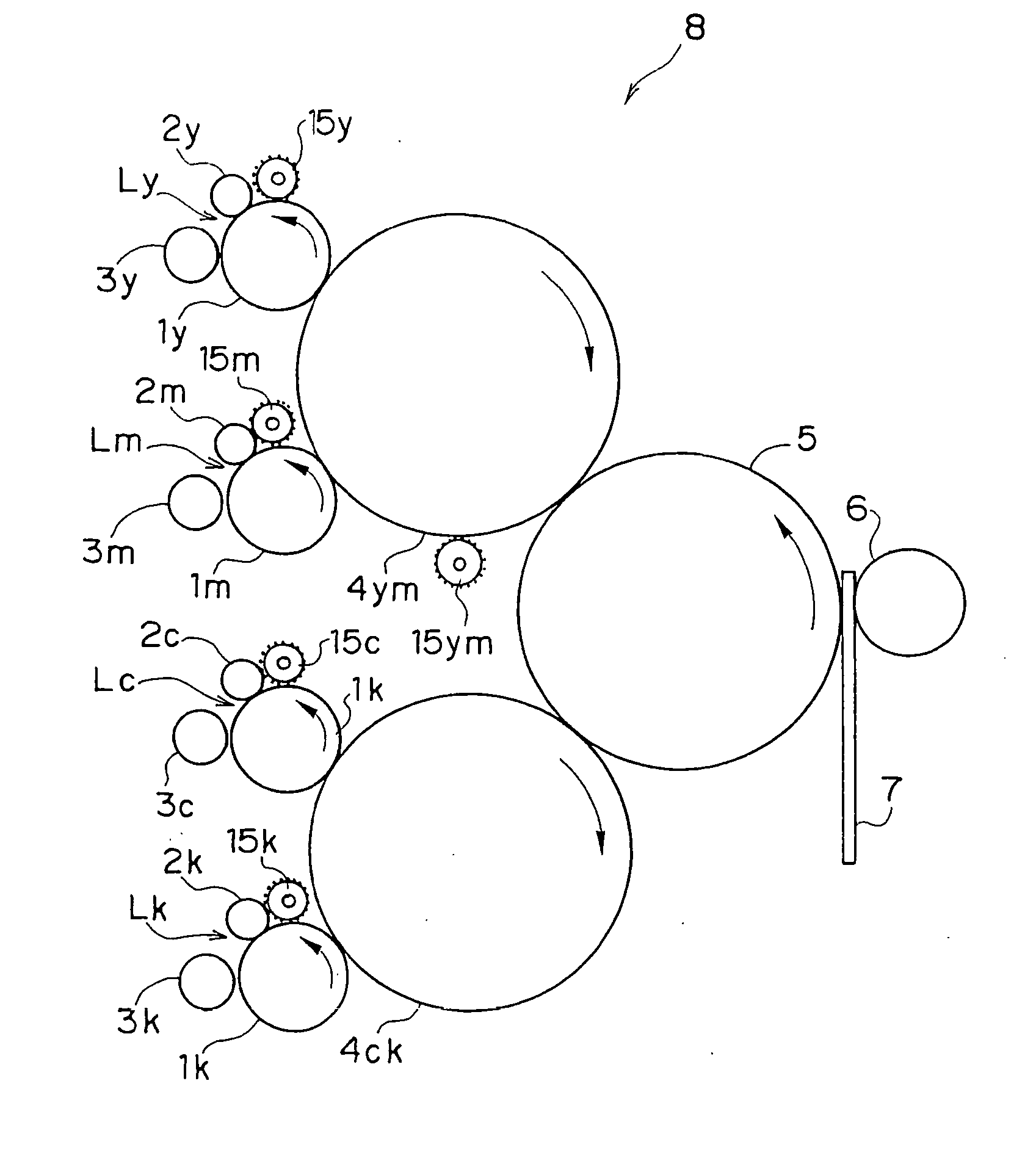
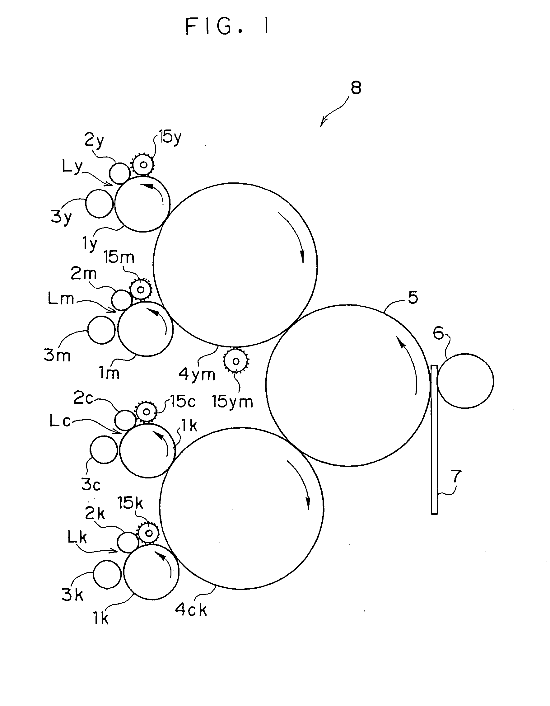
[0077] An image forming apparatus 8 of Example 1 employed a two-component developer and 3 denier fur brushes as brushes 15y, 15m, 15c and 15k on the surfaces of image holding members 1y, 1m, 1c and 1k. In the two-component developer, a toner concentration based on a carrier was 11% and a charging amount of the toner to a carrier was -35 .mu.C / g. The 3 denier fur brushes were made of nylon fibers with carbon dispersed therein, having a density of 230 kF / inch.sup.2.

[0078] In this image forming apparatus 8 of Example 1, the number of remaining toner particles was 136 and a remaining toner shape change rate (Tt) was 70%.

[0079] Then, by the image forming apparatus 8 of Example 1, with respect to full color images of three patterns such as a letter, a half tone, a color skew, running tests were performed 30,000 times using an A4 size P paper (manufactured by Fuji Xerox Co., Ltd.) as the recording material 7, and occurrence of pollution of a contact-type charger and occurrence of toner fil...

example 2

[0080] An image forming apparatus 8 of Example 2 employed a two-component developer and 2 denier fur brushes as brushes 15y, 15m, 15c and 15k on the surfaces of image holding members 1y, 1m, 1c and 1k. In the two-component developer, a toner concentration based on a carrier was 11% and a charging amount of the toner to a carrier was -35 .mu.C / g. The 2 denier fur brushes were made of acrylic fibers with carbon dispersed therein, having a density of 100 kF / inch.sup.2.

[0081] In this image forming apparatus of Example 2, the number of remaining toner particles was 218 and a remaining toner shape change rate (Tt) was 80%.

[0082] Then, the same test as that of Example 1 was performed by the image forming apparatus 8 of Example 2. The results are shown in Table 1.

example 3

[0083] An image forming apparatus 8 of Example 3 employed the same members as those of Example 1 except in that in a two-component developer, the toner concentration based on a carrier was 10% and a charging amount of the toner to a carrier was -40 .mu.C / g.

[0084] In this image forming apparatus of Example 3, the number of remaining toner particles was 270 and a remaining toner shape change rate (Tt) was 95%.

[0085] Then, the same test as that of Example 1 was performed by the image forming apparatus 8 of Example 3. The results are shown in Table 1.


PUM


Abstract

An image forming apparatus containing an image holding member, a contact-type charger for charging a surface of the image holding member, an exposure unit for forming an electrostatic latent image by exposing the charged surface of the image holding member, a developing unit for developing the electrostatic latent image with a spherical toner to obtain a toner image, and a transfer member for electrostatically transferring the toner image from the surface of the image holding member onto a transfer material. A number of toner particles remaining on the surface of the image holding member before passing through an abutting portion between the image holding member and the contact-type charger is in a range of 100 to 400 per unit area (mm<2>).

Description

[0001] This application claims priority under 35USC 119 from Japanese Patent Application No. 2002-360834, the disclosure of which is incorporated by reference herein.[0002] 1. Field of the Invention[0003] The present invention relates to an image forming apparatus utilizing an electrophotographic method, such as a compact copying machine, a printer, a composite machine and the like, more particularly, an image forming apparatus which is improved for solving the inconvenience when using a substantially spherical toner. The present invention also relates to a process cartridge which is attachable to and detachable from the image forming apparatus.[0004] 2. Description of the Related Art[0005] In an image forming apparatus utilizing an electrophotographic method, image forming is performed by forming an electrostatic latent image on the surface of an image holding member composed of an organic photosensitive material or the like in the form of a drum or a belt by the known electrophoto...

Claims


Application Information

Patent Timeline
Patent Type & Authority Applications(United States)
IPC IPC(8): G03G9/08G03G15/08G03G21/00G03G21/10
CPCG03G21/0064
Inventor FURUKI, MANABUFUKUSHIMA, KOJIMAEKAWA, YOSHIHIROOHNISHI, NAOKIKASONO, JIN
Owner FUJIFILM BUSINESS INNOVATION CORP
Why Eureka
Try Eureka