System and method of wavefront sensing

a wavefront and wavefront technology, applied in the field of wavefront sensing methods and devices, can solve the problems of inefficient computation using zernike polynomials, and achieve the effect of improving the accuracy of center of mass computation and preserving the time advantage of the method

Active Publication Date: 2004-07-08
AMO DEVMENT
View PDF1 Cites 21 Cited by
  • Summary
  • Abstract
  • Description
  • Claims
  • Application Information

AI Technical Summary

Benefits of technology

0143] We have shown formally the well-known result that the shift in the focal spot location is proportional to the average wavefront slope across a lenslet. The result is exact in the isoplanatic and small angle limits. We then showed the relationship between the focal spot location and the center of mass computation. The accuracy of the assumption that the center of mass is the focal spot l

Problems solved by technology

Despite their role in optical analysis, computation using the Zernike polynomials is quite inefficient.
Even though Zernike polynomia

Method used


Image

  • System and method of wavefront sensing
  • System and method of wavefront sensing
  • System and method of wavefront sensing

Examples


Embodiment Construction

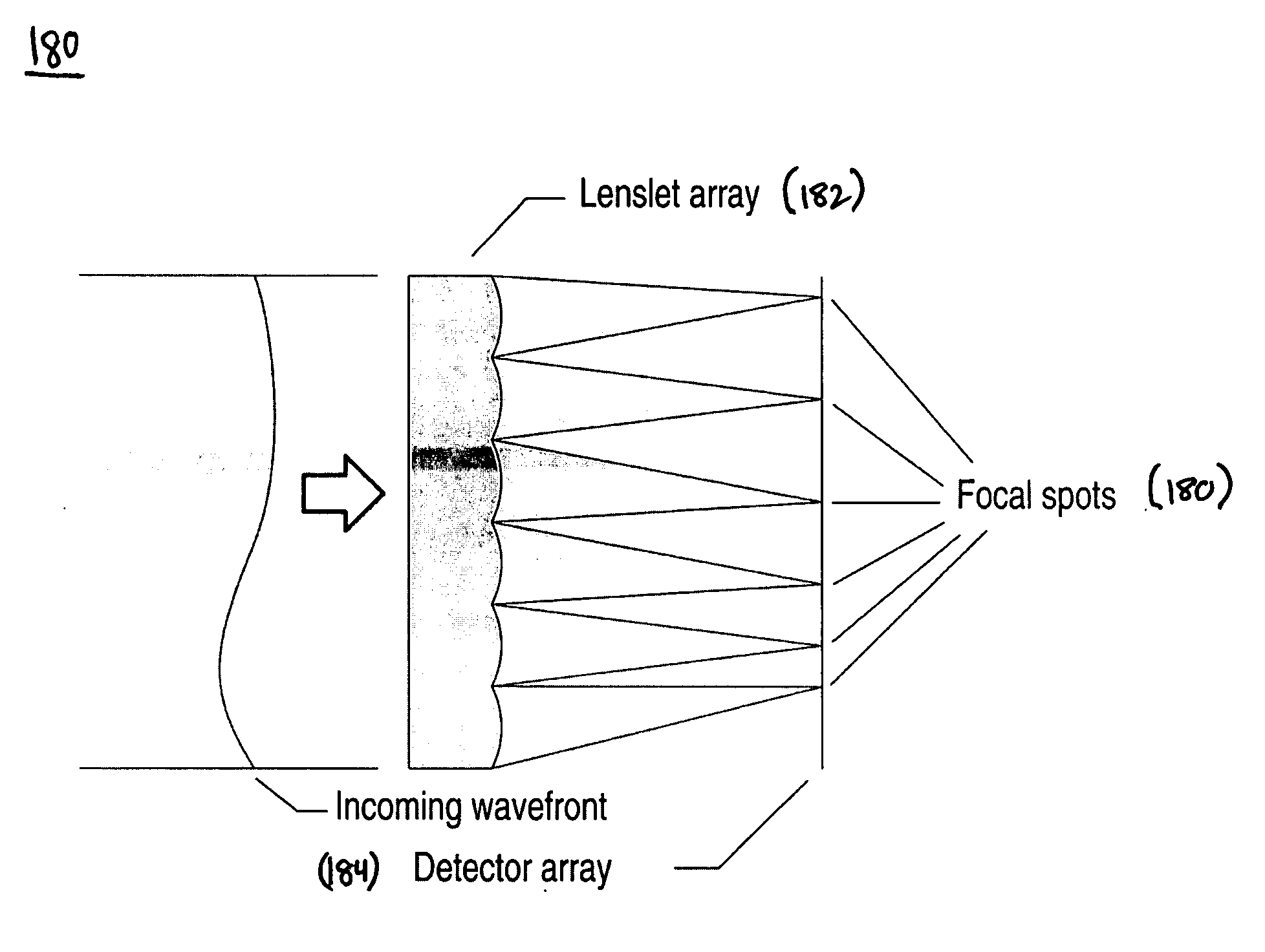
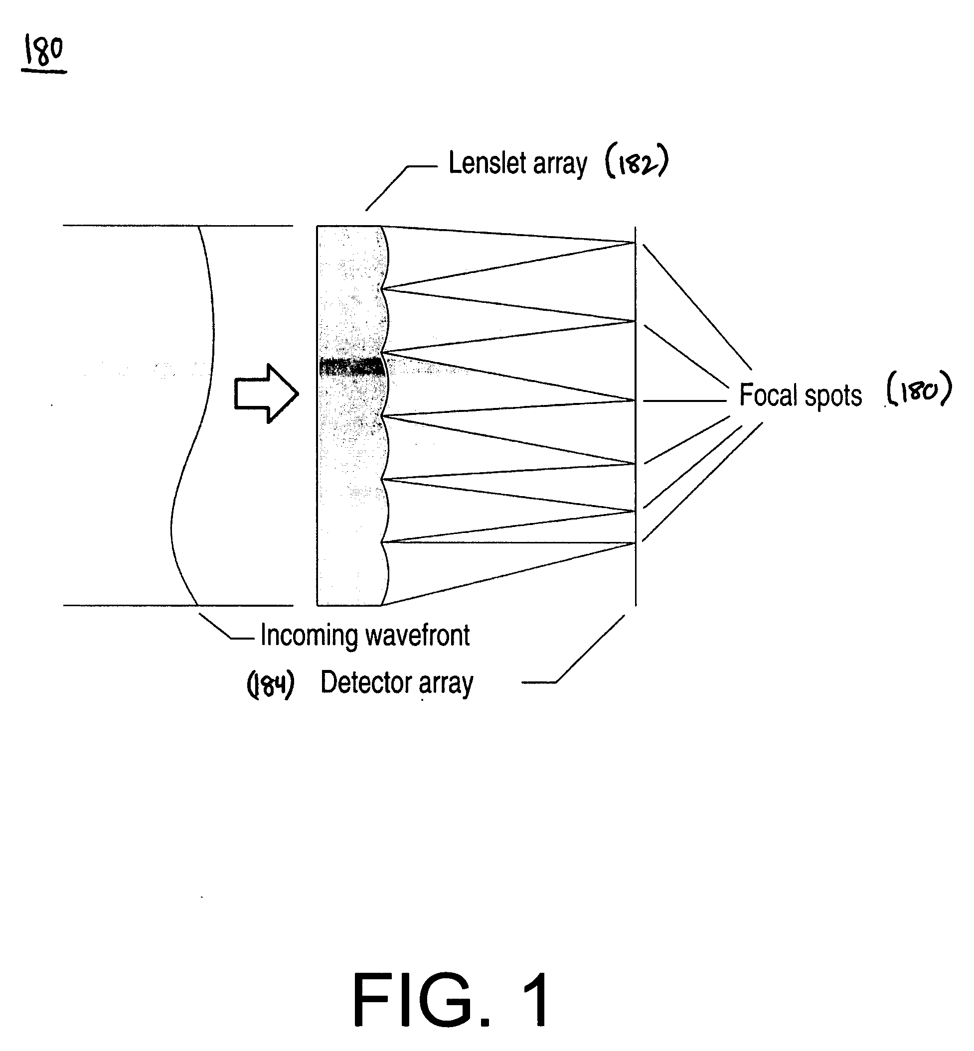
[0171] A sample lenslet and camera were chosen from the Columbus experimental configuration. This sensor uses a 60.times.60 array of square lenslets. Each lenslet is 280 .mu. across with a spherical profile and a focal length of 28 mm. The array is etched into fused silica and the lenslets have a 100% fill factor. The camera used was an SMD model 1M15, with a 14 .mu., pixels in a 1024.times.1024 grid. The output is digitized to 12 bits. The lenslet array was placed approximately 36 mm (1.3 focal lengths) from the CCD array.

[0172] 3.1 Single Measurement

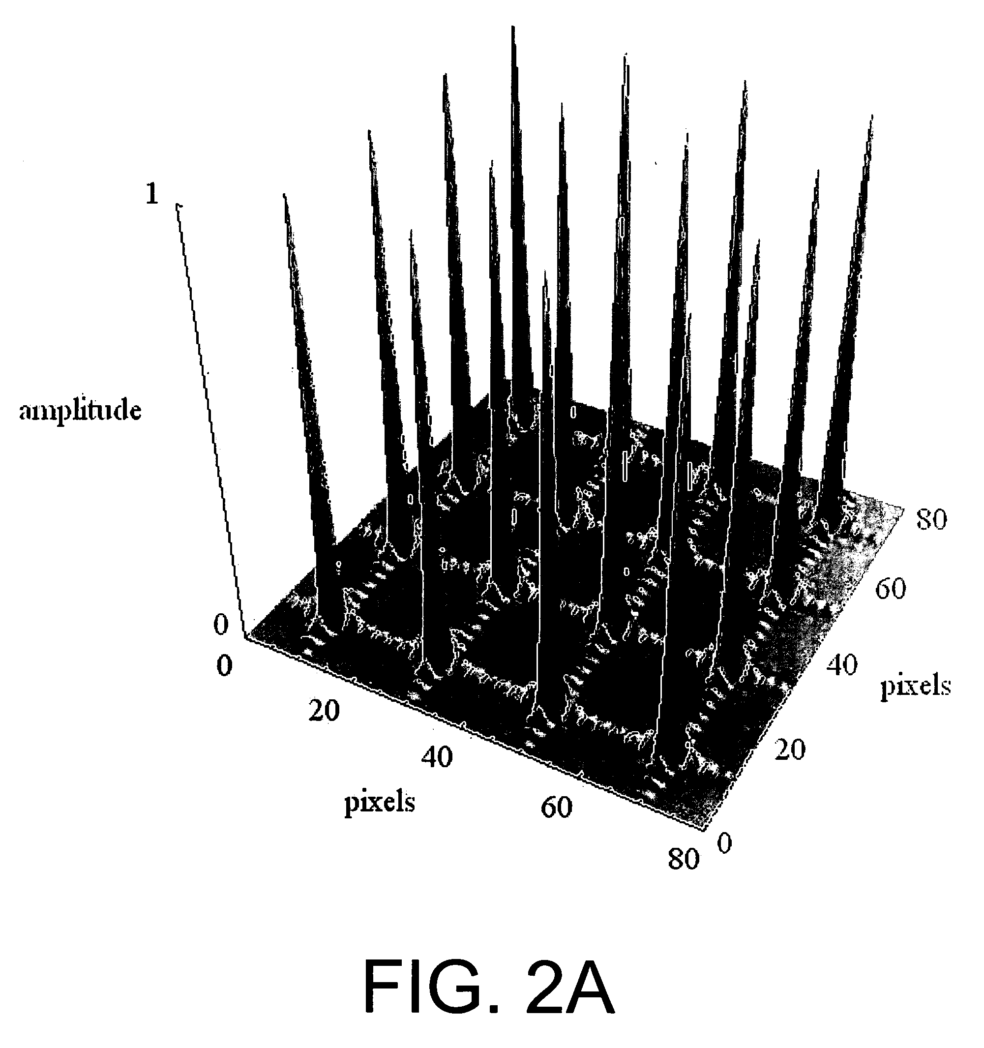
[0173] By design, the lenslet array is much larger that the CCD array, so a subset of the lenslets are used. Here we used a 50.times.50 subset of the lenslets. For these 2500 lenslets, the array, was found to be

[0174] size=20.0005.+-.0.0008.times.20.0025.+-.0.0008 pixels,

[0175] and the location of the origin of the array was found at the pixel address of

[0176] location=(16.92.+-.0.02, 15.58.+-.0.02) pixels.

[0177] The aspect ratio of th...


PUM


Abstract

A system and method of wavefront sensing with a Shack-Hartmann wavefront sensor precisely locates focal spots on a detector array, and determines the location of the lenslet array with respect to the detector array.

Description

[0001] This application claims priority under 35 U.S.C. .sctn. 119 to co-pending U.S. Provisional Patent Application No. 60 / 394,232, filed on 9 July 2002 in the name of Daniel M. Topa, the entirety of which is hereby incorporated by reference herein for all purposes as if fully set forth herein.[0002] 1. Technical Field[0003] This invention pertains to the field of wavefront sensing methods and devices, and more particularly, to a method and system for more precisely determining the location of a focal spot in a wavefront sensor, for more precisely determining the location of vertices or boundaries of lenslets in a lenslet array with respect to pixels of a wavefront sensor, for using this information to reconstruct an arbitrary wavefront with the wavefront sensor, and for more efficiently performing the calculations to perform the reconstruction.[0004] 2. Description[0005] A light wavefront may be defined as the virtual surface delimited by all possible rays having an equal optical ...

Claims


Application Information

Patent Timeline
IPC IPC(8): G01J9/00
CPCG01J9/00
Inventor TOPA, DANIEL M.
Owner AMO DEVMENT
Why Eureka
Try Eureka