Friction compensation in a vehicle steering system

a steering system and friction compensation technology, applied in the direction of steering initiation, instruments, vessel construction, etc., can solve the problems of road wheels not following the steering wheel command, limit cycles, stick-slip motion, and stable state errors, and achieve the effect of eliminating the effect of friction presen

Inactive Publication Date: 2004-07-15
NISSAN MOTOR CO LTD
View PDF2 Cites 47 Cited by
  • Summary
  • Abstract
  • Description
  • Claims
  • Application Information

AI Technical Summary

Benefits of technology

0009] A friction compensator in the steer-by-wire control system produces a friction compensating torque value equal and opposite in sign to the instantaneous friction torque. This compensating friction torque is added to the system control signal to eliminate the effects of friction present in the system. The friction compensator produc

Problems solved by technology

There are many sources of friction in such a system, including the ball screw bearings, the interface between the screw and the tie-rod, and the load and side load caused by the road wheels.
The resultant friction is highly nonlinear and may adversely affect the performance of the steering control system resulting in stead

Method used


Image

  • Friction compensation in a vehicle steering system
  • Friction compensation in a vehicle steering system
  • Friction compensation in a vehicle steering system

Examples


Embodiment Construction

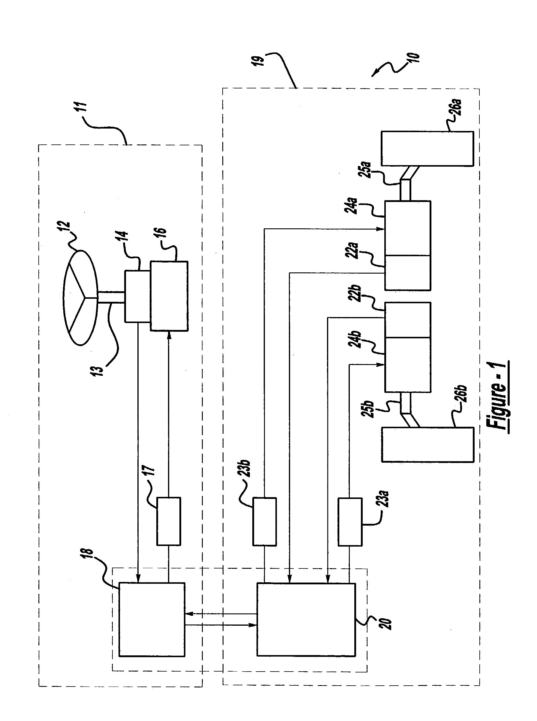
[0023] In accordance with its preferred embodiment, as shown in FIG. 1, the steer-by-wire system 10 of the present invention is generally composed of a steering wheel control system 11 and a road wheel control system 19. The steering wheel control system 11 includes a steering wheel 12 rotatable about a steering column 13. A steering wheel angle sensor 14 and a steering wheel motor actuator 16 are mounted on the steering shaft 13, and connected to a steering wheel control unit 18. A steering wheel motor amplifier 17 is used to drive the motor actuator 16.

[0024] The road wheel control system 19 includes a pair of road wheels 26a, 26b that are mechanically coupled to independent road wheel actuators 24a, 24b through tie rods 25a, 25b. The road wheel control system also includes a pair of road wheel angle sensors 22a, 22b for measuring the steer angle of the respective road wheels 26a, 26b. The road wheel actuators 24a, 24b and road wheel angle sensors 22a, 22b are connected to a road ...


PUM


Abstract

The present invention provides systems and methods of friction compensation in a steer-by-wire system or in a general electric steering system using control, estimation and modeling methodologies. A friction compensator in the steer-by-wire control system produces a friction compensating torque value equal and opposite in sign to the instantaneous friction torque. This compensating friction torque is added to the steering system control signal to eliminate the effects of friction present in the system such that the system performances are improved. The friction compensator produces the compensating friction torque according to one of two schemes: model-based or non-model based. The model-based scheme encompasses a number of different methods including a standard model-based scheme, a disturbance torque observer-based scheme, an adaptive friction compensation scheme, or a model reference adaptive control scheme. The non-model based scheme includes a fuzzy logic scheme.

Description

[0001] The present invention relates generally to friction compensation in a steering system for a vehicle and more particularly to friction compensation in a steer-by-wire system using model-based and non-model based friction compensation methodologies.BACKGROUND AND SUMMARY OF THE PRESENT INVENTION[0002] A typical automotive vehicle is steered by transmitting operations of a manually steerable device, such as a steering wheel, to a steering mechanism for directing the road wheels. Generally, the manually steerable device is located inside the vehicle passenger compartment, and the steerable road wheels are located at the front of the vehicle. Thus, a suitable steering mechanism is necessary to couple the manually steerable device and the road wheels.[0003] In order to overcome limitations presented by mechanical steering systems, it has been proposed to utilize a steering system in which the manually steerable device is not mechanically coupled to the road wheels and steering move...

Claims


Application Information

Patent Timeline
IPC IPC(8): B62D5/00B62D5/04
CPCB62D5/0463B62D5/001
Inventor YAO, YIXINASHRAFI, BEHROUZLERSEN, ANN HAYES
Owner NISSAN MOTOR CO LTD
Why Eureka
Try Eureka