Electronically programmable method for improving the control behaviour of an anti-lock braking control system

a control system and electronic programming technology, applied in the direction of braking systems, vehicle position/course/altitude control, instruments, etc., can solve the problems of insufficient utilization of brake potential and the operator's belief of being capabl

Inactive Publication Date: 2004-07-15
CONTINENTAL TEVES AG & CO OHG
View PDF4 Cites 8 Cited by
  • Summary
  • Abstract
  • Description
  • Claims
  • Application Information

AI Technical Summary

Benefits of technology

[0010] With a view to influencing yaw torque, pressure modulation is executed especially during ABS control intervention in dependence on a parameter .THETA. characterizing driving stability according to the invention. It is possible to consider said parameter in the partial braking range--outside of ABS control cycles.[0011] The invention permits an adaptive design of the anti-lock pressure modulation with influencing yaw torque in response to the degree of instability. The coefficient of friction available is better utilized because pressure build-up times generally increased by a defined coefficient are not envisaged on the high-wheel after pressure reduction. With short stopping distances, yaw torque is effectively influenced.[0012] Further details of the invention can be seen in the subclaims in connection with the description and the accompanying drawings. In the drawings,[0013] FIG. 1 is a flow chart of an embodiment of the invention.[0014] FIG. 2 shows signal variations .omega..sub.act, .omega..sub.LW, .DELTA..omega., .DELTA..omega. and parameter .THETA. as a function of time t.[0015] FIG. 3 shows signal variations .omega..sub.act, .omega..sub.LW, .DELTA..omega., .DELTA..omega., parameter .THETA. as well as pressure variations p.sub.VL, p.sub.VR respectively as a function of time t.[0016] FIG. 4 shows a maximum allowable pressure difference on wheel brakes of the front axle in dependence on a yaw rate .omega..sub.act.

Problems solved by technology

Not all vehicle operators consider themselves capable of keeping an unexpectedly yawing vehicle to the track.
Said GMA system suffers from the shortcoming that the brake potential is not fully utilized, because the high-wheel is generally underbraked to a great degree.

Method used


Image

  • Electronically programmable method for improving the control behaviour of an anti-lock braking control system
  • Electronically programmable method for improving the control behaviour of an anti-lock braking control system
  • Electronically programmable method for improving the control behaviour of an anti-lock braking control system

Examples


Embodiment Construction

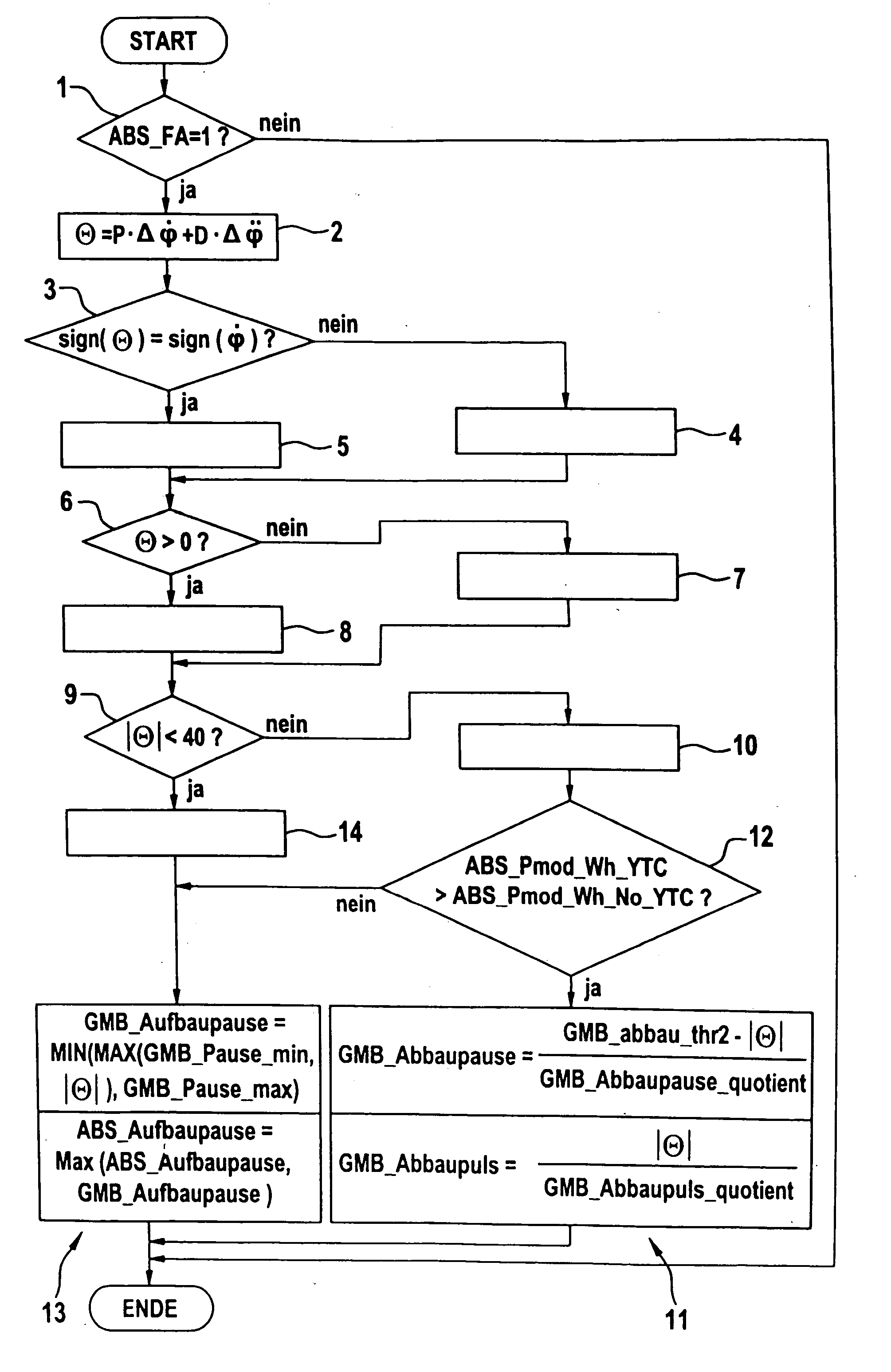
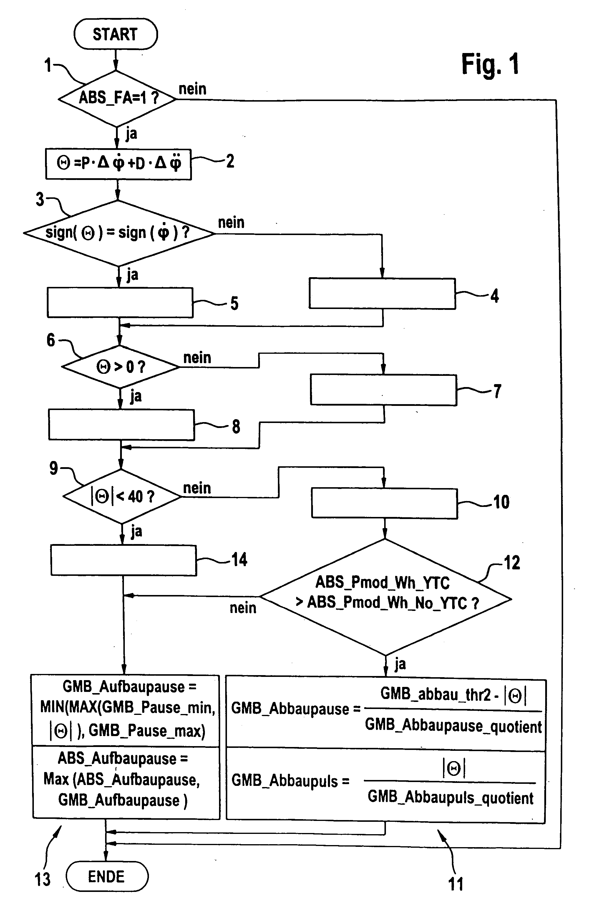
[0017] The method run will be explained schematically in the following by way of a flow chart according to FIG. 1. The operation starts when according to a criterion (ABS.sub.13 FA=1) mentioned at 1 an ABS control intervention is active on at least one wheel of the vehicle front axle. When this does not apply, the procedure is discontinued. The parameter .THETA.--hereinbelow referred to as stability index--is produced according to 2. Included in parameter .THETA. are both the yaw rate deviation .DELTA..omega. and the acceleration deviation .DELTA..omega. (time derivative of the yaw rate deviation). A comparison 3 of the signs of parameter .THETA. and yaw rate deviation .DELTA..omega. permits recognizing whether there is an understeering tendency (4) when the signs are different (which the driver is still able to master, as the case may be), which can be counteracted by pressure build-up modification 13, or whether there is a critical oversteering tendency 5 of the vehicle when the s...


PUM


Abstract

The present invention relates to a method for improving an anti-lock control system, in particular for improving driving stability during braking on laterally different coefficients of friction. According to the method, a desired yaw rate is determined using at least one steering angle signal of a steering angle sensor and an actual yaw rate is determined using at least one yaw rate sensor, and the instability is evaluated using a parameter that serves for a qualitative and quantitative judgment of a deviation between the actual yaw rate and the desired yaw rate. Both yaw rate deviation and the time derivative of the yaw rate deviation are used to determine the parameter.

Description

PRIOR ART[0001] The present invention relates to a method for improving an anti-lock control system, in particular for improving driving stability during braking on laterally different coefficients of friction.[0002] The wheel rotational behavior is measured and taken into account for determining the wheel slip and for brake pressure modulation in principally known control methods. In the wheel-individual control (individual control, single wheel control) of vehicle wheels, the brake pressure of each wheel is controlled irrespective of the rotational behavior of the other wheels. Admittedly, short braking distances can be achieved with this procedure. E.g. on roadways with a laterally divided friction situation (.mu.-split), however, a yaw torque about a vertical vehicle axis may develop, necessitating active countersteering by the vehicle operator for compensation in order to prevent undesirable change in the driving direction. Not all vehicle operators consider themselves capable ...

Claims


Application Information

Patent Timeline
Patent Type & Authority Applications(United States)
IPC IPC(8): B60T8/58B60T8/1755B60T8/1764
CPCB60T8/1764B60T8/1755
Inventor MAHLO, RUDIGERBURKHARD, DIETER
Owner CONTINENTAL TEVES AG & CO OHG
Why Eureka
Try Eureka