Retardation compensator and single-panel type color liquid crystal projector

a liquid crystal projector and compensator technology, applied in the direction of color television details, instruments, polarising elements, etc., can solve the problems of narrow viewing angle of liquid crystal devices, inability to increase the contrast ratio of projected images, and disadvantages of projection lens systems, so as to achieve the effect of reducing the size of the projector

Inactive Publication Date: 2004-07-22
FUJIFILM CORP
View PDF7 Cites 42 Cited by
  • Summary
  • Abstract
  • Description
  • Claims
  • Application Information

AI Technical Summary

Problems solved by technology

The liquid crystal device has the disadvantage of narrow viewing angle because of its birefringence.
Then, it is impossible to increase the contrast ratio of the projected image even if the observer changes the viewing angle.
Such projection lens system, however, is disadvantageous in terms of making the projector smaller.
Higher intensity of the light source causes excessive heat to the retardation compensator.
Because of such low durability, it is difficult to utilize the organic retardation compensator to the home use liquid crystal projection TV.
The retardation compensator made of sapphire or crystal has durability enough for long-term use, but the sapphire and crystal are expensive.
Accordingly, sapphire or crystal retardation compensator is not appropriate for household type liquid crystal projector in terms of manufacture cost, regardless of great durability.
However, such form birefringence causes wavelength dependence in compensating the phase retardation of the single-panel type liquid crystal projector to display a full color image.
Although the retardation of the liquid crystal device is compensated effectively, providing each pixel with the retardation compensation film suitable for the corresponding color light causes complicated manufacture process and increase the manufacture cost.

Method used


Image

  • Retardation compensator and single-panel type color liquid crystal projector
  • Retardation compensator and single-panel type color liquid crystal projector
  • Retardation compensator and single-panel type color liquid crystal projector

Examples


embodiment 1

[0087] [Embodiment 1]

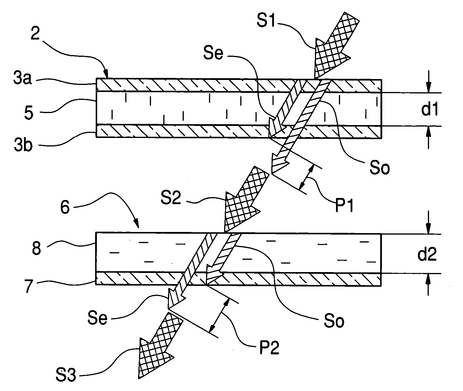
[0088] As shown in FIG. 7, the retardation d.multidot..DELTA.n of nematic liquid crystal material for the TN liquid crystal device has wavelength dependence. Note that the thickness d of the TN liquid crystal device (corresponding to d1 of the liquid crystal layer 5 in FIG. 1) is 4.5 .mu.m. Since all of the liquid crystal molecules in a black state pixel do not orientate perpendicularly, as mentioned above, it is assumed that 70% of the liquid crystal molecules in thickness d cause effective retardation Re to be compensated. The effective retardation Re, calculated by 0.7.times.d.multidot..DELTA.n, is also listed in FIG. 7.

[0089] In this embodiment, the liquid crystal device contains cyanocyclohexanes nematic liquid crystal, known as "ZLI-1083" (Trade Name) manufactured by Merck Ltd. The rate of the liquid crystal molecules to cause the effective retardation is not limited to 70%, but may be decided appropriately in accordance with composition and kind of the li...

embodiment 2

[0097] [Embodiment 2]

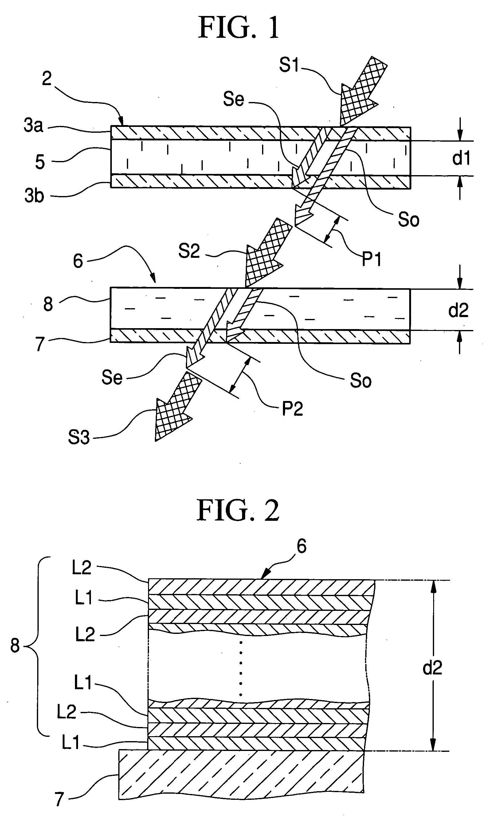
[0098] FIG. 10 shows the physical properties of the retardation compensation film (2) that is composed of 51 LiNbO.sub.3 film layers and 51 SiO.sub.2 film layers that are alternately layered on a substrate. The LiNbO.sub.3 film layer is used as the high refractive index layer, whereas The SiO.sub.2 film layer is used as the low refractive index layer. The physical thicknesses of the LiNbO.sub.3 film layer and the SiO.sub.2 film layer are 27.5 nm and 22.5 nm, respectively. The physical thickness of the retardation compensation film (2) is 2.55 .mu.m in total. Compared with the Embodiment 1, the birefringence value .DELTA.n of the retardation compensation film (2) is smaller, because the refractive index of the LiNbO.sub.3 film layer is smaller than that of the TiO.sub.2 film layer. However, the wavelength dependence of the retardation compensation film (2) has improved. Referring to FIG. 11 that shows the graph of the wavelength dependence, the retardation (.tang...

embodiment 3

[0099] [Embodiment 3]

[0100] FIG. 12 shows the physical properties of the retardation compensation film (3) that is composed of LiNbO.sub.3 film layers and MgF.sub.2 film layers that are alternately layered on a substrate. The LiNbO.sub.3 film layer is used as the high refractive index layer, whereas the MgF.sub.2 film layer is used as the low refractive index layer. The thickness and the number of the LiNbO.sub.3 film layer and MgF.sub.2 film layer are the same embodiment 1. Referring to FIG. 13 that shows the graph of the wavelength dependence, it is found that the retardation compensation film (3) has the similar retardation compensation characteristics as the retardation compensation film (2) according to Embodiment 2.

[0101] As mentioned in the above embodiments, the birefringence value .DELTA.n of the retardation compensation film 8 becomes large as the difference in the refractive indices between high and low refractive index layers increases. Thus, when the physical thickness ...


PUM

PropertyMeasurementUnit
thicknessaaaaaaaaaa
thickness ratioaaaaaaaaaa

Abstract

A form birefringence to compensate the phase retardation caused by a liquid crystal device has a retardation compensation film that is composed of alternately deposited high and low refractive index layers. The retardation compensation film is provided in at least one of the incident side and the emanation side of the liquid crystal device. The birefringence value Deltan and the total thickness d of the retardation compensation film are adjusted such that the retardation of the retardation compensation film agrees with the retardation of the liquid crystal device at least at one wavelength in the visible band.

Description

[0001] 1. Field of the Invention[0002] The present invention relates to a retardation compensator that is suitable for a liquid crystal projector having single liquid crystal device for full color display, and a single-panel type color liquid crystal projector having the retardation compensator.[0003] 2. Description of the Related Art[0004] Besides the three-panel type liquid crystal projector with three liquid crystal devices for blue, green and red images, there are single-panel type liquid crystal projectors. In the single-panel type liquid crystal projector, blue, green and red lights, separated by space division system or time division system, enter the single liquid crystal device. The liquid crystal device has plural pixels arranged in matrix to modulate the corresponding color lights based on the pixel image data. In the space division system, each pixel of the liquid crystal device is illuminated by each of the three color lights. In order to achieve this, as described in U...

Claims


Application Information

Patent Timeline
Patent Type & Authority Applications(United States)
IPC IPC(8): G02B5/30G02F1/1335G02F1/13363
CPCG02B5/3083G02F1/133526G02F1/13363G02F2001/133637H04N9/3108G02F2203/02G02F2203/04G02F2413/10G02F2413/13G02F2001/133638G02F1/133637G02F1/133638
Inventor NAKAGAWA, KENICHI
Owner FUJIFILM CORP
Why Eureka
Try Eureka