Eureka AIR delivers breakthrough ideas for toughest innovation challenges, trusted by R&D personnel around the world.

Optical packet routing network system based on optical label switching technique

a network system and optical label technology, applied in data switching networks, multiplex communication, transmission monitoring, etc., can solve the problems of increasing the size and cost of communication nodes, increasing the burden of electrical routing processes, and reducing so as to reduce the load of electrical processing, reduce the burden of electrical processing, and simplify the system

Inactive Publication Date: 2004-07-22
NIPPON TELEGRAPH & TELEPHONE CORP
View PDF9 Cites 3 Cited by
  • Summary
  • Abstract
  • Description
  • Claims
  • Application Information

AI Technical Summary

Benefits of technology

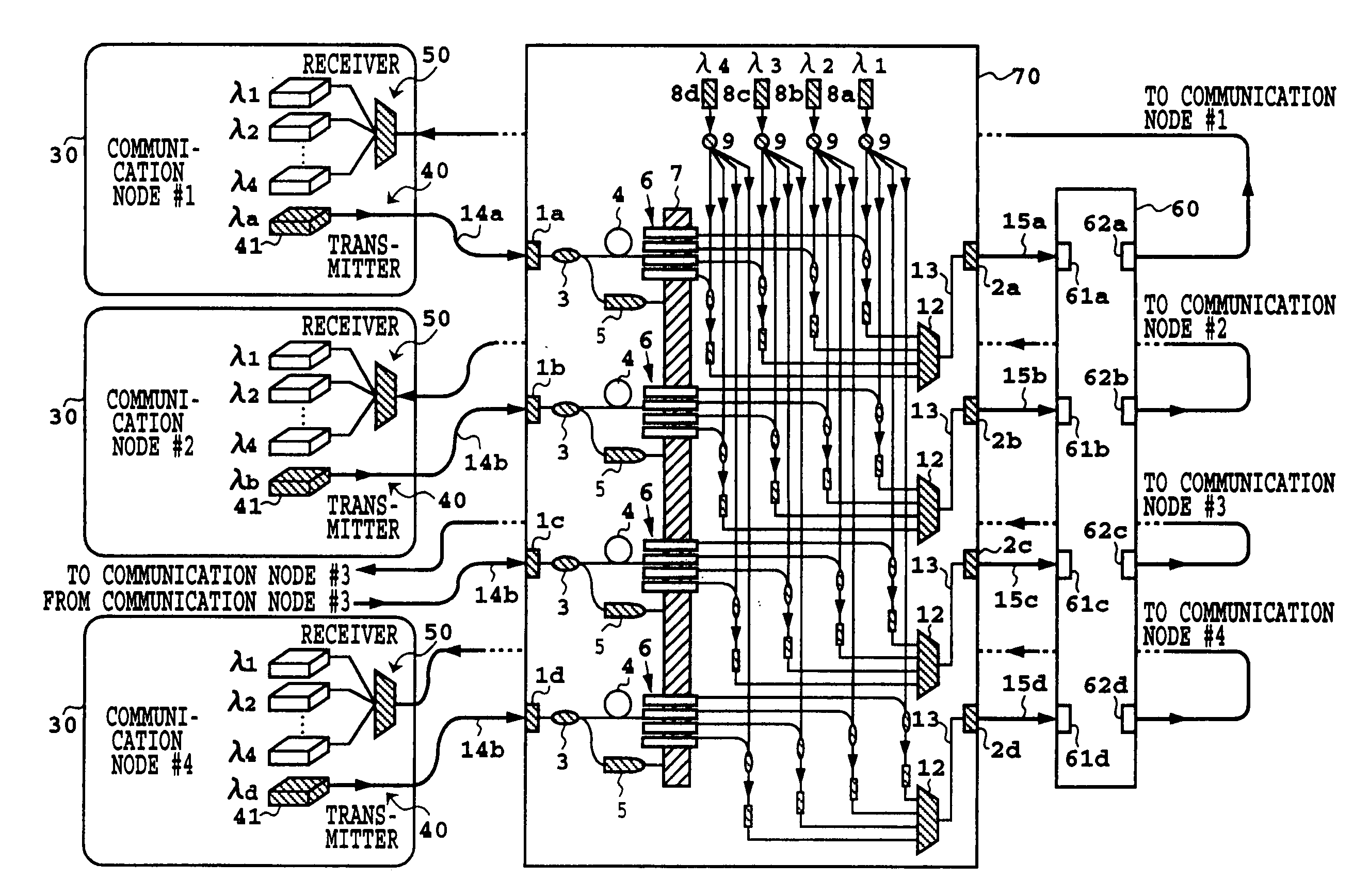
0102] As explained in the foregoing, according to the first embodiment of the present invention, in a network system comprising a plurality of communication nodes which are connected with one another by the wavelength routing method, since a multi-wavelength optical source equipment comprises shared multi-wavelength optical sources to be shared among individual communication nodes and wavelength conversion function provided between each communication node and each wavelength router, the wavelength of the optical signal transmitted from each communication node can be converted into the wavelength adapted for the routing to the desired communication node by the output lights from the shard multi-wavelength optical sources, whereby, in consequence, the number of optical sources employed for data transmitting to be provided for each of the plural communication nodes, which are connected with one another by the wavelength routing method, can be reduced largely for the building of a low-cost system.
0103] Further, since the multi-wavelength optical source equipment having the shared multi-wavelength optical sources to be shared among individual communication nodes is provided, the wavelength of the principal optical signal transmitted from each communication node is converted into the wavelength adapted for the wavelength routing by the multi-wavelength optical source equipment, so that it is not necessary to allocate the optical sources having a strictly defined wavelength for data transmission, thereby making the composition of the system easier.
0104] Further, since the multi-wavelength optical source equipment comprising the shared multi-wavelength optical sources to be shared among the individual communication nodes, though the transmission bit-rate of the data increases, it is possible to reduce the load of the electrical processing for reading the routing information of the data by transmitting the routing information of the data with a low bit-rate optical signal having the wavelength differing from the data signal.
0105] Furthermore, since the multi-wavelength optical source equipment comprising the shared multi-wavelength optical sources to be shared among individual communication nodes, the status information of data transmissions from the communication nodes can be converged to the multi-wavelength optical source equipment, so that the control of the network can be made easier.
0106] Composition Example 2 of the First Embodiment
0112] The wavelength converters 20a-20d with the optical gate function can be used as the substitutes for the optical gates 6 and the wavelength converters 10a-10d shown in FIG. 8, so that the number of parts can be reduced further.

Problems solved by technology

However, with the exponential-growth in the communication traffic, in the near future, the routing processing capacity by the electrical routing processes is considered to reach its limit.
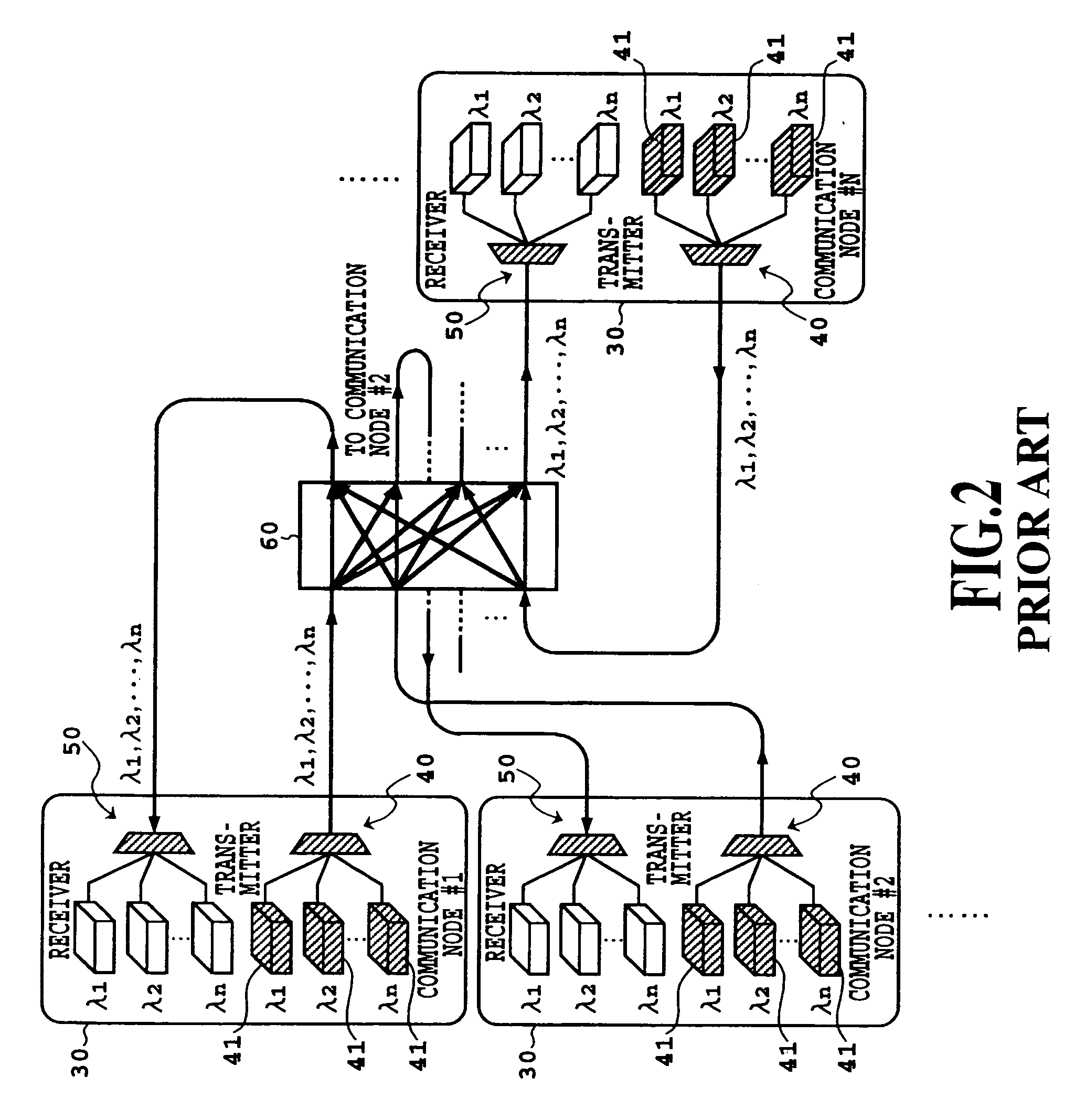
However, in the case of conventional network system as is shown in FIG. 2, especially in the case of the network comprising N number of communication nodes, it is necessary to provide N number of optical sources with wavelengths strictly adapted to the wavelength characteristic of the cyclic-wavelength arrayed-waveguide grating with respect to each of the communication nodes and thus requiring N.times.N number of optical sources, which is a problem to be resolved.
Especially, providing N number of optical sources for each communication node not only results in the increase in the burdens such as the increase in the size and cost of the communication node but also results in the increase in total cost of the network system.
However, since the router and each communication node are, in general, arranged at physically separated locations, when setting the previously mentioned transmission time lag T at each communication node, it is necessary to adjust in real-time conjunction so that the data is transmitted properly to each communication node, but this process is very cumbersome in the case of the conventional system.

Method used


Image

  • Optical packet routing network system based on optical label switching technique
  • Optical packet routing network system based on optical label switching technique
  • Optical packet routing network system based on optical label switching technique

Examples


first embodiment

of the First Embodiment

[0107] Next, the composition example 2 of the first embodiment of the present invention will be explained referring to FIG. 9. The parts of this composition shared to those of the basic composition shown in FIGS. 7 and 8 are given shared numerals and symbols and the explanation thereof are omitted here.

[0108] This example is a variation of the basic composition shown in FIG. 8. In the case of the multi-wavelength optical source equipment 70 shown in the FIG. 8, the outputs ports of the optical splitter 9 for branching the optical signal passing the second optical path 23 to a plurality of optical paths are respectively connected to the optical gates 6.

[0109] In contrast, in the case of the present embodiment, as shown in FIG. 9, wavelength converters 20a-20d, having optical gate function respectively, are respectively connected between each pair of the wavelength multiplexer 11 and the wavelength multiplexer 12, located respectively in the stage following the ...

example 4

[0121] [Composition Example 4 of the First Embodiment]

[0122] Next, the composition example 4 of the first embodiment of the present invention will be explained referring to FIG. 12. The parts shared to those of the previous example are given shared numerals and symbols and the explanation thereof is omitted.

[0123] This example is a variation of the basic composition shown in FIG. 8. That is, the multi-wavelength optical source equipment 70 incorporates the cyclic-wavelength arrayed-waveguide grating 60 as an optical component having the wavelength routing function.

[0124] In the cases of various composition examples including the first embodiment of the present example, the cyclic-wavelength arrayed-waveguide grating 60 is employed as an optical component having the wavelength routing function, but the components other than this component may be used as long as the latter have the functions equivalent to that of the former.

[0125] Composition Example 5 of the First Embodiment

[0126] Ne...

example 6

[0136] [Composition Example 6 of the First Embodiment]

[0137] Next, the composition example 6 of the first embodiment of the present invention will be explained referring to FIG. 14. The parts shared to those of the preceding example are given shared numerals and the symbols and the explanation thereof are omitted.

[0138] This example is a variation of the composition example 5. To be specific, the multi-wavelength optical source equipment 70 incorporates the wavelength demultiplexer 31 for separating the principal optical signal and the optical signal for control differing in wavelength from the principal optical signal and the cyclic-wavelength arrayed-waveguide grating 60 as an optical component having the wavelength routing function.

[0139] The cyclic-wavelength arrayed-waveguide grating 60 is employed as an optical component having the wavelength routing function, but any other component having the equivalent function may also be employed as a substitute.


PUM


Abstract

An optical communication equipment comprises shared optical sources 88a-88d to be shared by communication nodes 100a-100d, the wavelengths of optical signals 76a-76d are converted into desired wavelengths lambdaa-lambdad according to the addressed information of the corresponding optical label signals 77a-77d by using the shared optical sources 88a-88d, and routed to the addressed communication nodes without being converted into electrical signals by using the wavelength routing function of the cyclic-wavelength arrayed-waveguide grating (AWG) 120. The load of each communication node can be reduced by incorporating the multi-wavelength optical sources, which can be shared among individual communication nodes, into the router 80. Further, each communication node is provided with an optical gate or the like for returning the optical signal to the communication node from which the optical signal has een transmitted through the router 80 in order to adjust the transmission time lag between the optical signal and the corresponding optical label signal by the controllers 110a-110d.

Description

[0001] This application is a divisional of U.S. patent application Ser. No. 09 / 644,324, filed on Aug. 23, 2000, which claims priority to Japanese Patent Application Nos. 238,794 / 1999 filed Aug. 25, 1999 and 070,872 / 2000 filed Mar. 14, 2000, the contents of which are incorporated herein by specific reference.[0002] 1. Field of Invention[0003] The present invention relates to an optical packet routing system for routing an optical signal by using the optical label signal carrying the control information necessary for the routing of the optical signal, more particularly, to a multiple-wavelength optical source unit to be used for a network system whose a plurality of communication nodes are connected by the wavelength routing system and an optical communication unit and an optical communication method to be used for an optical communication system whose internode communication among the communication nodes is made through a routing unit.[0004] 2. Description of the Art[0005] With the e...

Claims


Application Information

Patent Timeline
Patent Type & Authority Applications(United States)
IPC IPC(8): H04L12/56H04B10/00H04Q11/00
CPCH04Q11/0005H04Q11/0062H04Q11/0066H04Q2011/0011H04Q2011/0083H04Q2011/0032H04Q2011/0041H04Q2011/0069H04Q2011/0073H04Q2011/0016H04B10/00H04B10/27
Inventor OKADA, AKIRAKATO, KAZUTOSHINOGUCHI, KAZUTOSAKAI, YOSHIHISASAKAMOTO, TAKASHIMATSUOKA, MORITOSUZUKI, SEN-ICHI
Owner NIPPON TELEGRAPH & TELEPHONE CORP
Why Eureka
Eureka Blog
Learn More