Hex-axis horizontal movement dynamic simulator

a dynamic simulator and hex-axis technology, applied in the direction of variable height tables, instruments, furniture parts, etc., can solve the problems of inconvenient replacement of parts and components in maintenance work, and achieve the effect of improving the efficiency of maintenance work

Inactive Publication Date: 2004-07-29
INTERNET MOTION NAVIGATOR CORP
View PDF12 Cites 61 Cited by
  • Summary
  • Abstract
  • Description
  • Claims
  • Application Information

AI Technical Summary

Benefits of technology

0009] Another purpose of the invention is to provide a specific structure of the modular movement control unit which can precisely control the movement of the load-carrying platform, and enable a structure of motion simulation platform having 6 degrees of freedom.

Problems solved by technology

Moreover, since the parts and components constructing the conventional Stewart Platform are not in modular design, and the inherent drawback of oil and air leakage problem occasionally occurred with hydraulic and pneumatic system are always bother some that resulted in the inconvenience and disadvantage of replacing the parts and components in maintenance work.

Method used


Image

  • Hex-axis horizontal movement dynamic simulator
  • Hex-axis horizontal movement dynamic simulator
  • Hex-axis horizontal movement dynamic simulator

Examples


first embodiment

[0045] What shall be mentioned here is that the sliding seat (24) employed in the second type of embodiment and the same in the first embodiment can be exchanged and used in either of the two types of embodiment, or in other embodiments of the invention.

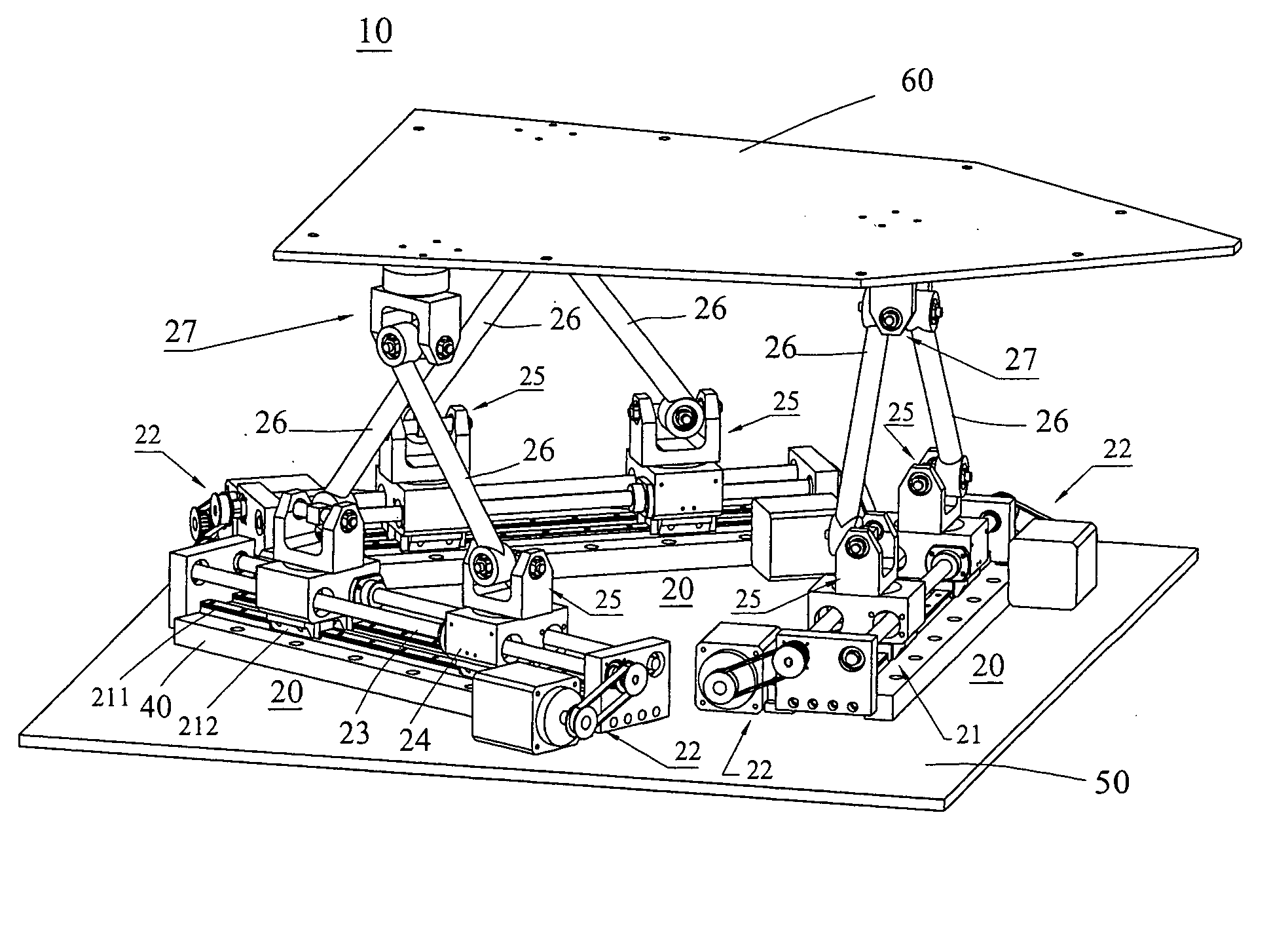
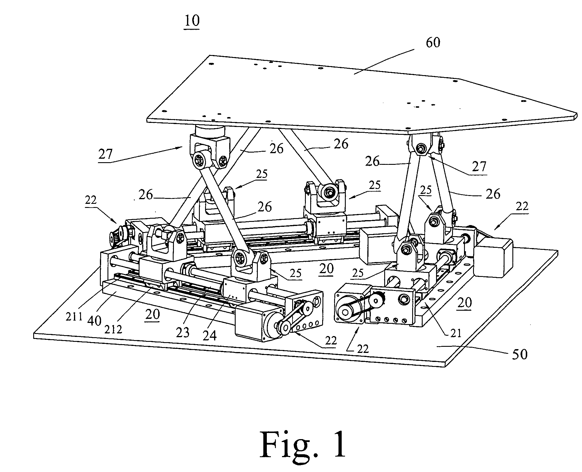
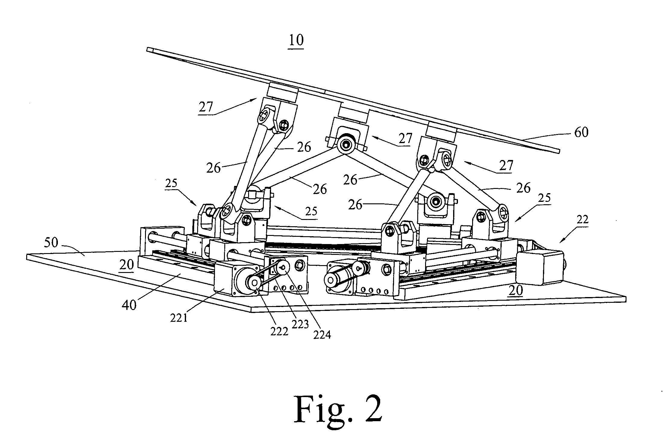
[0046] The third type of embodiment of the movement control unit (20) is shown in FIG. 7 and FIG. 8 which compresses at least a base seat (40), a set of universal-joint yoke mechanism (29), two connecting rods (26) of fixed length, two sets of sliding yoke mechanism (28), two leading screws (23), two sets of servo-driving mechanism (22) and a rectilinear translation guide (21) wherein the said connecting rod (26), lead screw (23), servo-driving mechanism (22) and rectilinear translation guide (21) are the same as those employed in the first type of embodiment, and the structure of the universal-joint yoke mechanism (29) is similar to the sliding yoke mechanism (28).

third embodiment

[0047] The universal-joint yoke mechanism (29) of the aforesaid third embodiment comprises an inversed U shaped yoke assembly (291), a pivoting plate (293), a pivoting shaft (295), two fixing blocks (296), a L shaped yoke plate (297), a fastening yoke plate (298) and two cover plates (299). The L shaped yoke plate is formed by a horizontal portion and a vertical portion. The horizontal portion is fastened on the load-carrying platform (60), and on the vertical portion hole is provided for mounting shaft. The fastening yoke plate (298) is a plate shaped member with appropriate thickness having appearance symmetric to that of the vertical portion of the L shaped yoke plate (297). Shaft mounting hole is also provided on the fastening yoke plate (298) which is to be assembled with the L shaped yoke plate (297) to form a yoke assembly. The pivoting plate (293) is in rectangular shape with a pivoting access in its center position and horizontal stub shafts (294) extended symmetrically fro...


PUM


Abstract

A hex-axis horizontal movement dynamic simulator is aimed at Modular Design without hydraulic or pneumatic system but which were conventionally used in the so called Stewart Platform; this dynamic simulator comprises three sets of movement control unit with symmetrical structure located at the positions relative to each other forming three sides of an equilateral triangle, and a load-carrying platform which connected to the three movement control by means of three sets of universal-joint yoke mechanism each relative position located on the load-carrying platform are each other arranged to form as three sides of an equilateral triangle too; with this type of arrangement, this dynamic simulator have a 6-degree of freedom motion when a sets of movement control unit makes different rectilinear motion, the load-carrying platform will generate a combination of spatial translation motion and angular motion.

Description

BACKGROUND OF THE PRESENT INVENTION[0001] 1. Field of the Present Invention[0002] This invention relates to a hex-axis horizontal movement dynamic simulator, particularly to a 6-degree of freedom motion simulating equipment in modular design.[0003] 2. Description of Prior Art[0004] Since the structure of the 6-degree of freedom motion simulating platform in the early years was proposed by the Englishman Steward, this type of 6-degree of freedom motion simulating platform was customarily called the Stewart Platform.[0005] For a long time, there was no any significant breakthrough of improvement or invention in the mechanism design of Stewart Platform which was still confined in the traditional idea of employing hydraulic or pneumatic system to achieve the effect of changing the length of the actuating rod by varying the stroke of cylinder rod to enable a 6-degree of freedom spatial motion. Moreover, since the parts and components constructing the conventional Stewart Platform are not...

Claims


Application Information

Patent Timeline
Patent Type & Authority Applications(United States)
IPC IPC(8): B25J11/00A47B91/16B25J17/02G09B9/02
CPCA47B91/16B25J17/0266Y10T74/20329B25J9/0042G09B9/02
Inventor CHIANG, JOHNSON
Owner INTERNET MOTION NAVIGATOR CORP
Why Eureka
Try Eureka