Substrate heating device and method of purging the device

a heating device and substrate technology, applied in the direction of coatings, metallic material coating processes, chemical vapor deposition coatings, etc., can solve the problems of difficult to ensure the accuracy of a wafer surface, prone to weak mechanical strength, and difficulty in ensuring uniformity

Inactive Publication Date: 2004-08-05
TOKYO ELECTRON LTD
View PDF12 Cites 26 Cited by
  • Summary
  • Abstract
  • Description
  • Claims
  • Application Information

AI Technical Summary

Problems solved by technology

However, such a long columnar structure is apt to be weak in mechanical strength and further accompanied with a problem of difficulty to ensure the accuracy of a wafer surface.
Additionally, due to the provision of a long heat transmission route, the columnar structure has a problem with difficulty to ensure uniformity of heat for the mount table because

Method used


Image

  • Substrate heating device and method of purging the device
  • Substrate heating device and method of purging the device
  • Substrate heating device and method of purging the device

Examples


embodiment

[0134] (8th. Embodiment)

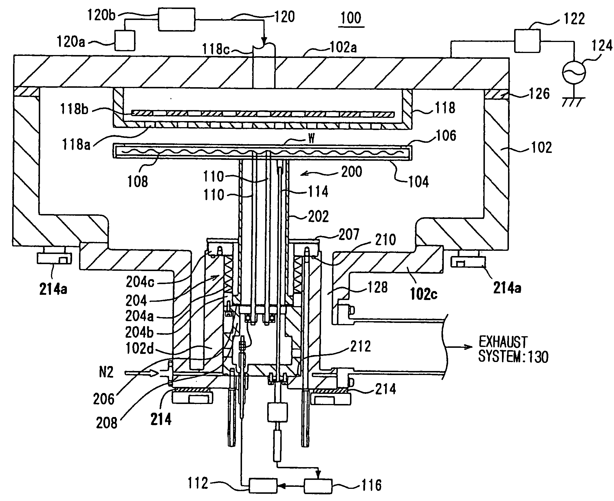
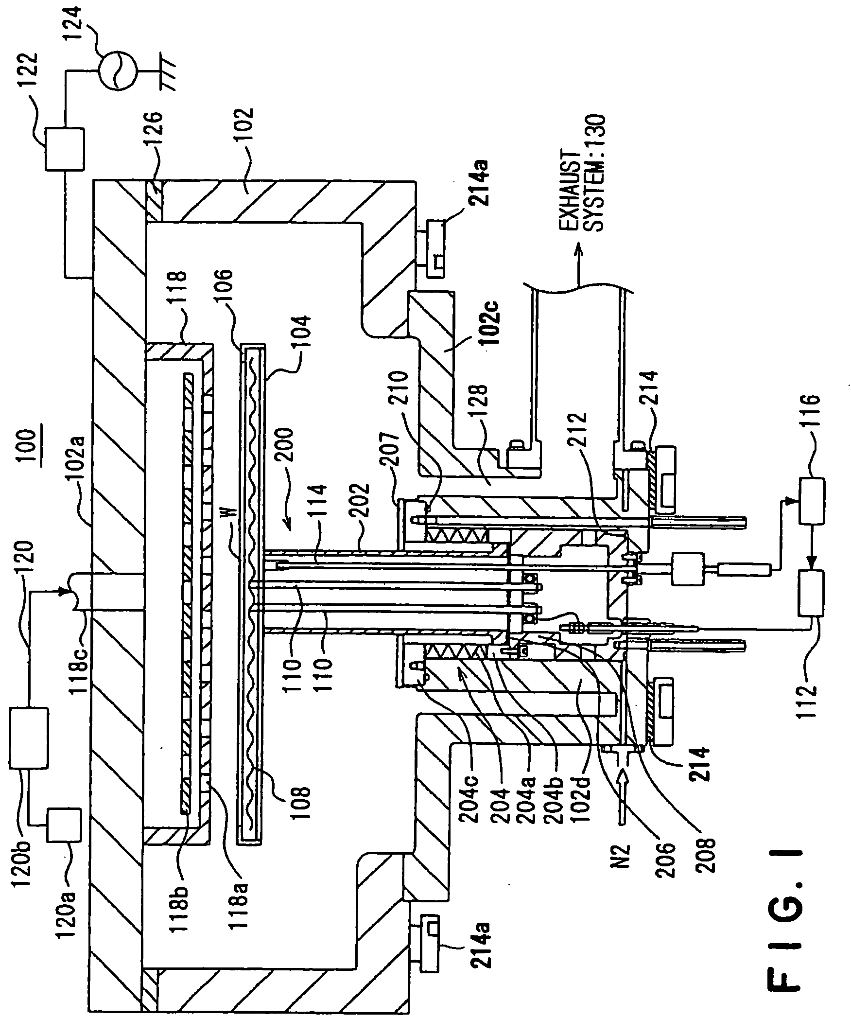
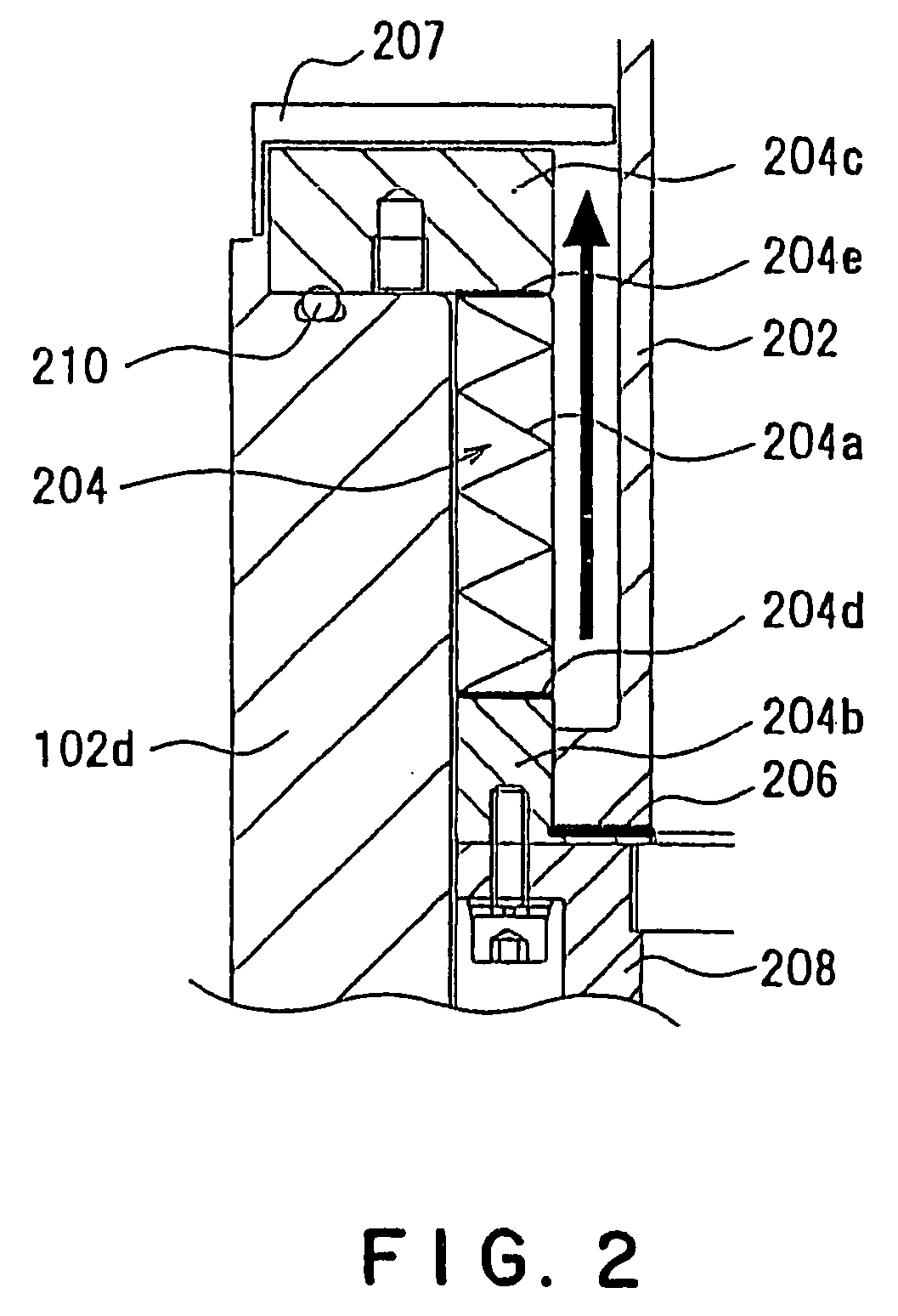
[0135] Next, the substrate heating apparatus in accordance with the eighth embodiment of the present invention will be described with reference to FIGS. 13 and 14. Note, in this embodiment, elements similar to those of the substrate heating apparatus of FIGS. 1 to 12 in terms of function and constitution are indicated with the same reference numerals respectively and their overlapping descriptions are eliminated.

[0136] In the first to sixth embodiments, the characteristic part resides in the supporting structure of the apparatus. In this embodiment, as similar to the seventh embodiment, the characteristic part resides in the constitution of a heater as the heating means of the mount table.

[0137] According to the substrate heating apparatus of this embodiment, a heater embedded in a mount table 704 replaceable for the mount table 604 of the seventh embodiment comprises an outer heater 709 and an inner heater 710 both of which site a common wiring 708 thereunde...


PUM

PropertyMeasurementUnit
Poweraaaaaaaaaa
Heightaaaaaaaaaa
Vacuumaaaaaaaaaa

Abstract

A substrate heating apparatus of the present invention, which heats a substrate mounted on a mount table 104 having heating means 108, in a processing vessel 102, includes a supporting part 202 made from a first material to support the mount table, a sealing part 204 made from a second material different from the first material in heat conductivity to seal the supporting part and the processing vessel and a joint part 206 for joining the supporting part and the sealing part in an airtight manner. With the constitution, by selecting the first material and the second material of different heat conductivities properly, it is possible to reduce a heat gradient between the top of the mount table and the bottom of the mount table. As a result, it is possible to shorten a supporting structure for the mount table, in length.

Description

[0001] The present invention relates to a substrate heating apparatus and a purging method thereof.BACKGROUND OF ART[0002] In the manufacturing process of semiconductor devices, a deposition system for forming a film by using a chemical vapor deposition (CVD) method is adopted widely.[0003] The deposition system employs a structure that creates a plasma from a deposit gas introduced into a processing vessel and further forms a film on a substrate mounted on a mount table. The deposition system is equipped with a substrate heating apparatus enabling heating of a substrate mounted on a mount table having heating means, such as heater.[0004] Although the mount table forming a part of the substrate heating apparatus is supported by a supporting structure where feeding means, such as power line, and sensor means, such as thermo couple, are arranged, it is necessary to seal the supporting structure and the processing vessel in vacuum in order to insulate the interior of the processing ves...

Claims


Application Information

Patent Timeline
IPC IPC(8): C23C16/44C23C16/458C23C16/46H01L21/00H01L21/205H01L21/22H01L21/285H01L21/687
CPCC23C16/4401C23C16/4408C23C16/4411C23C16/4586H01L21/68792H01L21/67103H01L21/67109H01L21/67115H01L21/67098
Inventor SAITO, TETSUYAKASAI, SHIGERU
Owner TOKYO ELECTRON LTD
Why Eureka
Try Eureka