Wire braid-reinforced microcatheter
a wire braided, micro-catheter technology, applied in the direction of catheters, coatings, etc., can solve the problems of high viscosity of embolizing materials, pressure may exceed the burst pressure of nearly all conventional pressure, etc., to achieve high degree of flexibility, high pressure, and high degree of strength
- Summary
- Abstract
- Description
- Claims
- Application Information
AI Technical Summary
Benefits of technology
Problems solved by technology
Method used
Image
Examples
example 1
[0052] According to one example of the present invention, two catheters were formed of the materials and by the steps described below.
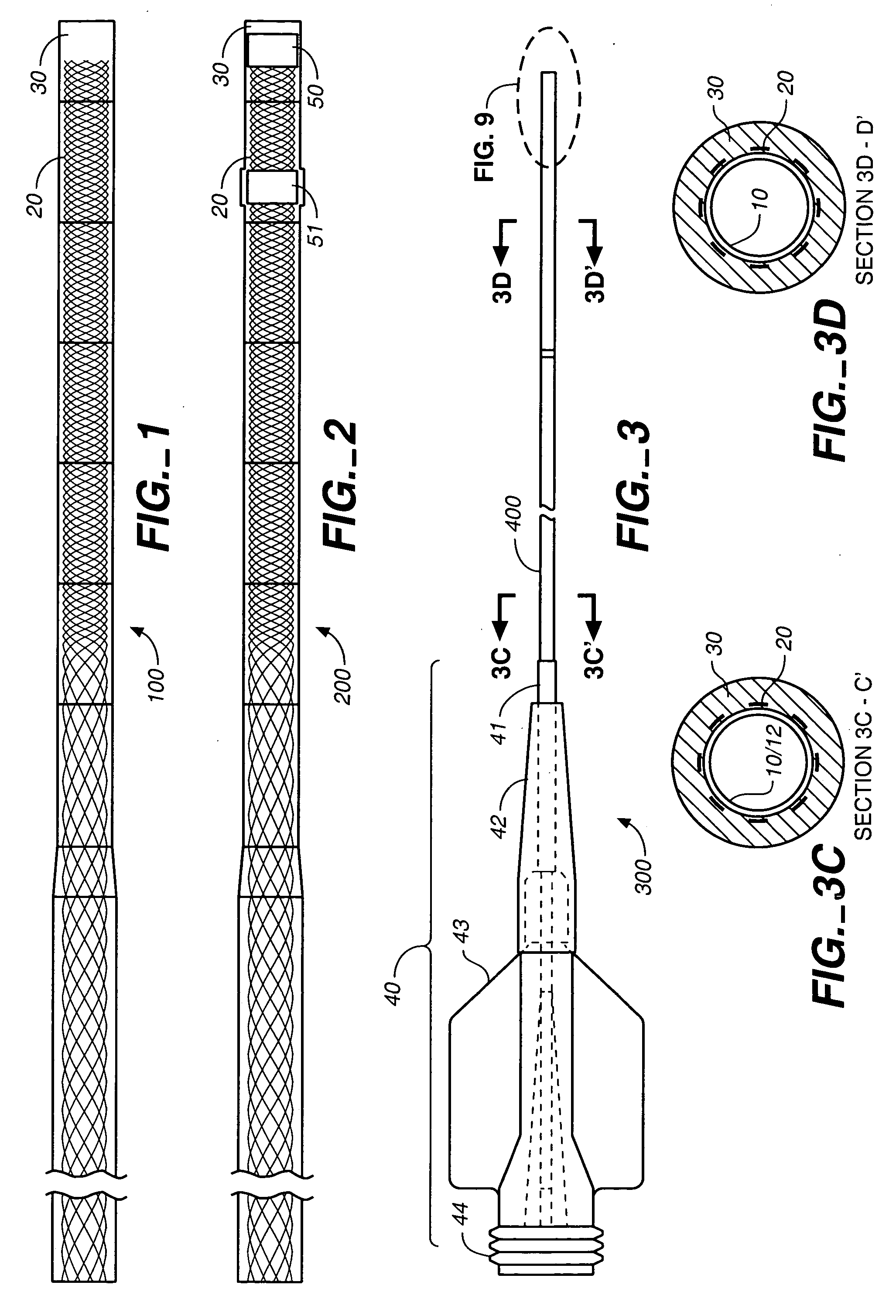
[0053] Two different Nitinol braids were cut to 155 cm in length for use in formation of the two catheters. The braids were each formed of eight elliptical 0.001".times.0.003" wires. The braids were formed on a steeger braider with the braider pitch changed between segments to form a continuous braid with a changing pitch The first braid had the following segments with the following pics-per-inch (ppi) starting from the distal end: 4 inches 120 ppi, 8 inches 70 ppi, 2 inches 40 ppi, 6 inches 30 ppi, and 39 inches 16 ppi. The second braid had the following segments starting from the distal end: 2 inches 120 ppi, 6 inches 110 ppi, 2 inches 50 ppi, 4 inches 40 ppi, 6 inches 30 ppi, and 39 inches 16 ppi. The remainder of the steps and materials were the same for the two catheters.
[0054] A liner of a polyimide layer overlapping a PTFE layer was purchased p...
example 2
[0058] A microcatheter was constructed as follows. A PTFE liner coated along its proximal end with polyimide was obtained. The polyimide coating was tapered between the coated and uncoated regions. The liner had an inside diameter of 0.17 inch (0.43 mm) and was more flexible in its uncoated region than in its coated region. This liner was placed on a suitable mandrel.
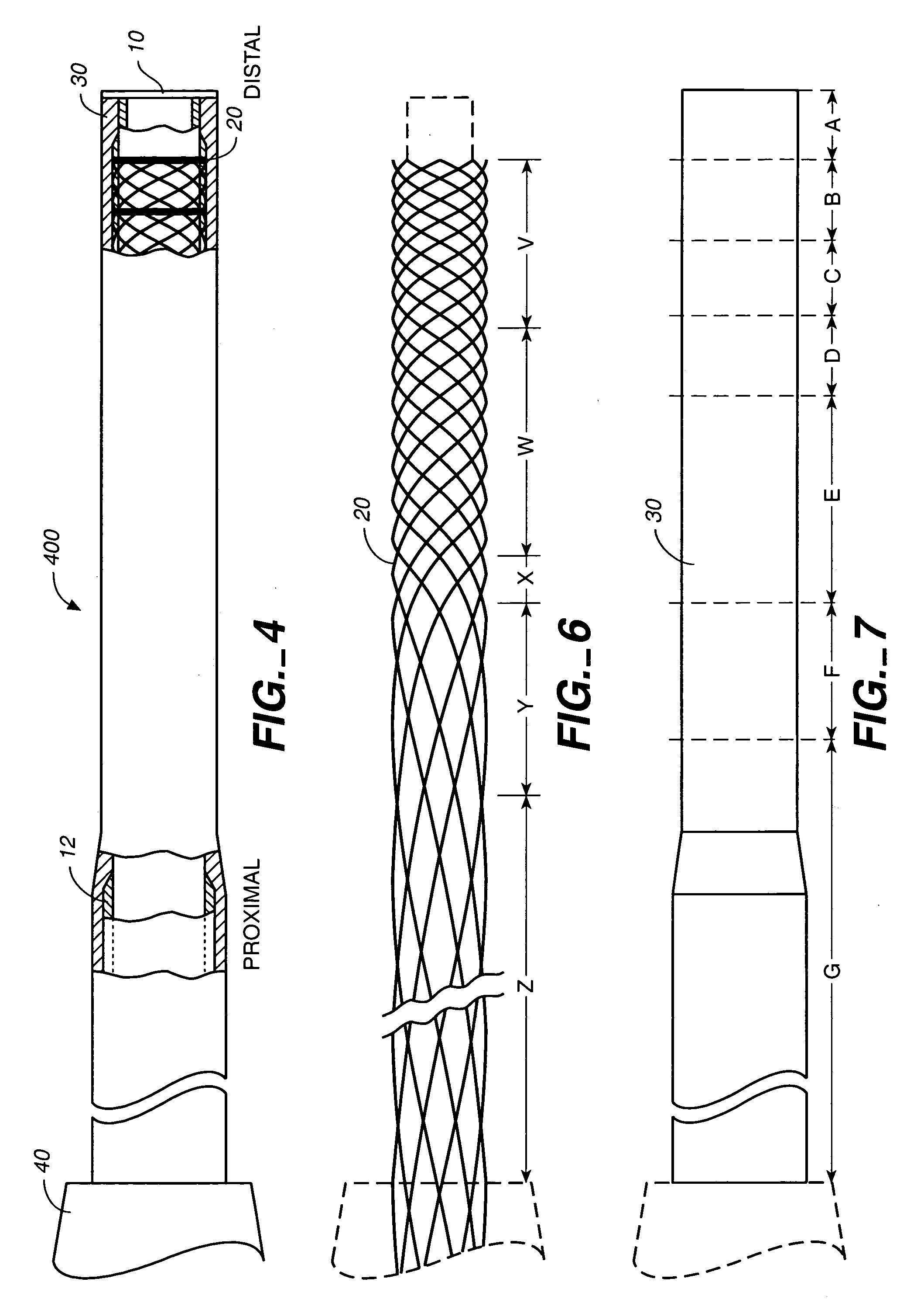
[0059] A Nitinol braid of the general type set out in Example 1 was obtained. This braid had 5 sections with the following five different pic per inch rates as shown in FIG. 6 and Table 3.
5 TABLE 3 Nominal Section Section Pic / Inch Length Distal V 120 15 cm. W 80 15 cm. X 50 5 cm. Y 30 15 cm. Proximal Z 25 100+ cm.
[0060] The braid was placed over the liner with the transition from 25 Pic to 30 Pic weave aligned somewhat distal to the end of the polyamide coating on the PTFE liner.
[0061] A polymer jacket was prepared by heat fusing seven cylindrical sections of polymers of varying stiffness to one another. The sections we...
example 3
[0067] Example 2 was repeated with the following changes:
[0068] The wire braid was made of 0.003.times.0.0007" elliptical wire, jacket section A was 25 durometer polyether / polyamide and the final outside diameter of the finished catheter was 1.7F (0.57 mm-0.023") at the distal end and 2.1F (0.70 mm-0.028") at the proximal end.
PUM
| Property | Measurement | Unit |
|---|---|---|
| Length | aaaaa | aaaaa |
| Length | aaaaa | aaaaa |
| Angle | aaaaa | aaaaa |
Abstract
Description
Claims
Application Information
 - R&D
- Intellectual Property
- Life Sciences
- Materials
- Tech Scout
- Unparalleled Data Quality
- Higher Quality Content
- 60% Fewer Hallucinations
Browse by: Latest US Patents, China's latest patents, Technical Efficacy Thesaurus, Application Domain, Technology Topic, Popular Technical Reports.
© 2025 PatSnap. All rights reserved.Legal|Privacy policy|Modern Slavery Act Transparency Statement|Sitemap|About US| Contact US: help@patsnap.com


