Honeycomb filter and exhaust gas purification system

a technology of exhaust gas purification system and honeycomb filter, which is applied in the direction of machine/engine, chemical/physical process, surface covering, etc., can solve the problems of high-pressure loss of honeycomb filter, clogging of filter, and gradual accumulation of solids such as ash and iron oxide which cannot be removed by combustion

Active Publication Date: 2004-08-19
NGK INSULATORS LTD
View PDF5 Cites 93 Cited by
  • Summary
  • Abstract
  • Description
  • Claims
  • Application Information

AI Technical Summary

Problems solved by technology

However, the honeycomb filters of the above configuration have a problem of a high-pressure loss since all through channels are plugged on one end face.
However, in a conventional honeycomb filter, solids such as ash and iron oxide which cannot be removed by combustion are gradually accumulated and clog the filter.
Therefore, such conventional honeycomb filters have a problem in thermal shock resistance due to heat expansion and the like of the plugging portions on the end face on the inlet port side.
For this reason, it has been difficult to use such filters for purifying exhaust gas from gasoline engines discharging exhaust gas at a temperature higher than that of diesel engines in a temperature fluctuation range greater than that of diesel engines.
In addition, particulate matters adhere to the plugging portions of through channels on the end face on the exhaust gas inlet port side of the honeycomb filters and deposit around the adhered particulate matters as a core, causing even the openings of the through channels of which the end face is not plugged on the exhaust gas inlet port side to clog.
This causes another problem of rapidly increasing a pressure loss in the filter.

Method used


Image

  • Honeycomb filter and exhaust gas purification system
  • Honeycomb filter and exhaust gas purification system
  • Honeycomb filter and exhaust gas purification system

Examples


Embodiment Construction

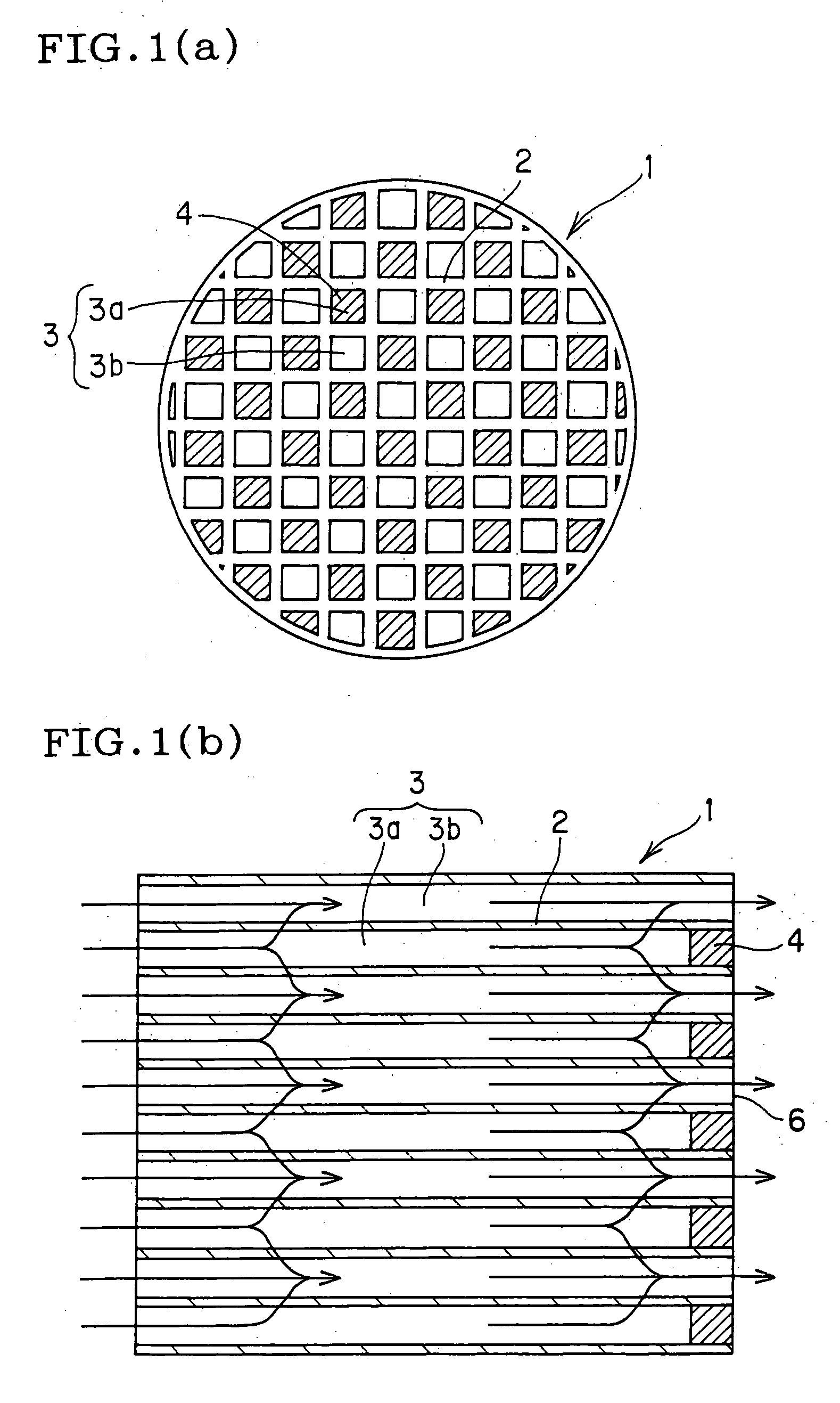
[0027] FIG. 1 is a general illustration diagram of one embodiment of the honeycomb filter of the first invention, wherein (a) is a plan view from one end and (b) is a cross-sectional view. The honeycomb filter of the first invention comprises a honeycomb structure having a large number of through channels 3 formed in the axial direction and partitioned by porous partition walls 2, wherein a part of large number of the through channels 3a is plugged only at one end face at the same side out of the two end faces. As an example of the honeycomb structure which can be suitably used for this honeycomb filter, a honeycomb structure made of cordierite having an external diameter of 190.5 mm and a length of 203.2 mm, through channels with a square cross-sectional form (cell form), a cell pitch of 1.6 mm, and a partition wall thickness of 0.3 mm manufactured by extrusion molding can be given.

[0028] In the honeycomb filter used as a conventional DPF and the like, through channels 13 are plugg...


PUM

PropertyMeasurementUnit
thicknessaaaaaaaaaa
thicknessaaaaaaaaaa
lengthaaaaaaaaaa

Abstract

A honeycomb filter comprises a honeycomb structure having a large number of through channels formed in the axial direction and partitioned by porous partition walls, wherein specified through channels are plugged only on one end face at the same side out of two end faces. This honeycomb filter shows less pressure loss, and is hardly clogged with solids that cannot be extinguished by combustion such as ash, iron oxide, and the like. Furthermore, an unwanted discharge of particulates deposited in through channels of the filter in a larger amount due to pulsation even under conditions that the exhaust gas from an engine greatly pulsates can be effectively suppressed. This filter is also usable as an element for exhaust gas purification system, or a part of composite filter in addition to the use for an exhaust gas purification filter for gasoline engines. The production method therefor is also disclosed.

Description

FIELD OF THE INVENTION AND THE RELATED ART STATEMENT[0001] The present invention relates to a honeycomb filter used to collect particulate matters in exhaust gas discharged from combustion engines such as a diesel engine.[0002] A large amount of particulate matters (fine particulate substances) including soot (a black smoke of carbon) as a major component are contained in exhaust gas discharged from a diesel engine, gasoline lean burn engine, or gasoline direct-injection engine. Since particulate matters cause environmental pollution if emitted into the atmosphere, a filter to collect the particulate matters is mounted in the exhaust gas system for a diesel engine.[0003] The honeycomb filter used for such a purpose has a honeycomb structure having many through channels 13 partitioned by porous partition walls 12 running in the axial direction as shown in FIGS. 10(a) and 10(b). One end of a part of the through channels 13a are plugged on one end face 16 and one end of the remaining t...

Claims


Application Information

Patent Timeline
Patent Type & Authority Applications(United States)
IPC IPC(8): F01N3/02B01D39/20B01D46/00B01D46/24B01D53/94B01J35/04C04B35/185C04B35/195C04B35/478C04B35/565C04B35/581C04B37/00C04B38/00F01N3/021F01N3/022F01N3/023F01N3/035F01N3/24F01N3/28F01N13/02
CPCB01D46/0001F01N13/0097B01D46/2451B01D46/2459B01D46/2466B01D53/944C04B35/185C04B35/195C04B35/478C04B35/565C04B35/581C04B37/005C04B38/0006C04B38/0016C04B38/008C04B2111/00793C04B2111/0081C04B2237/062C04B2237/341C04B2237/343C04B2237/346C04B2237/348C04B2237/363C04B2237/365C04B2237/366C04B2237/368C04B2237/78C04B2237/88F01N3/022F01N3/0222F01N3/035F01N3/2803F01N3/2828F01N2250/02F01N2330/02F01N2330/06F01N2330/30F01N2510/06F01N2510/063F01N2570/10F01N2570/12F01N2570/14B01D46/0024C04B35/00C04B38/0012B01D46/64
Inventor ICHIKAWA, YUKIHITOYAMADA, TOSHIO
Owner NGK INSULATORS LTD
Why Eureka
Try Eureka