Extremely long wire fasteners for use in minimally invasive surgery and means and methods for handling those fasteners

a technology of wire fasteners and wire fasteners, which is applied in the direction of surgical staples, applications, veterinary instruments, etc., can solve the problems of difficult manipulation of tools, knots, and methods that must be effectiv

Inactive Publication Date: 2004-08-26
MEDTRONIC INC
View PDF11 Cites 349 Cited by
  • Summary
  • Abstract
  • Description
  • Claims
  • Application Information

AI Technical Summary

Benefits of technology

[0026] It is a main object of the present invention to provide an anchoring and termination system that can be used in minimally invasive surgery.

Problems solved by technology

However, even though speed is important, the fastener must be capable of reliable and secure placement since a non-secure fastener can have undesirable results, especially if leak-paths could be formed adjacent a non-secure fastener.
In addition, since access is so limited, methods must be effective.
The problem is that a long needle driver needed for the minimally invasive access makes it difficult to manipulate the tools and even more difficult to tie knots at a remote location and there is little time savings realized.
Surgeons therefore have had a difficult time replicating their current techniques with subtle improvements to their existing tools when modified for minimally invasive surgery.
This is due in part to the limited space associated with minimally invasive surgery.
Also, this is due to restricted "in-line" viewing which is all one can obtain when viewing down a small and narrow tunnel-like incision used in minimally invasive surgical procedures.
In other words, the procedure will most likely take longer and require greater surgeon skill than would a standard non-minimally invasive operation.
This will hamper the growth of minimally invasive procedures.
Still further, it is very undesirable for a suture to come out of the tissue or the item being anchored to the tissue.
This can be a problem in older patients with brittle or frail tissue.
Thus, a leak free joint is essential, but cannot be obtained at the expense of tearing the patient's tissue.
Thus, the amount of force applied is not easily reduced.
Yet a further problem with some prosthetic heart valves and the prior implanting procedures associated therewith is that there are unwanted projections remaining on the implanted item.
Blood clots tend to form around foreign objects in the body.
However, there is a danger that the formed blood clots may dislodge into the patient's blood stream which may cause a major problem such as stroke.
This leaves raw edges exposed to the patient's blood stream.
Loose clots in the bloodstream are dangerous for the patient as they have the potential for producing a stroke.
Clots forming on sutures may also extend into the valve and produce malfunctions by trapping the valve open or shut.
Still further, the exposed surfaces can become a site for infection.
Circulating bacteria may become attached and lead to infection at the implanted device.
Such infections are notoriously difficult to treat with antibiotics.
However, in the case of minimally invasive surgery, the surgeon cannot get his or her hand into position to feel the knot and thus ensure proper tension.
Still further, installing multiple suture pairs can be time consuming and can be difficult.
There is data available which indicates that because the suture is manipulated with the surgeon's gloved hand during the knot-tying process required by prior art procedures, it is susceptible to contamination from pin hole leaks in those gloves.
Still further, some patients have tissue that is thicker than other patient's tissue, or is more fragile than other patient's tissue or the like.
Thus, a fastener that is suitable for one patient's tissue may not be suitable for another patient's tissue.
However, the prior art fasteners have legs that are of a preset length.
This is cumbersome and inefficient.

Method used


Image

  • Extremely long wire fasteners for use in minimally invasive surgery and means and methods for handling those fasteners
  • Extremely long wire fasteners for use in minimally invasive surgery and means and methods for handling those fasteners
  • Extremely long wire fasteners for use in minimally invasive surgery and means and methods for handling those fasteners

Examples


Embodiment Construction

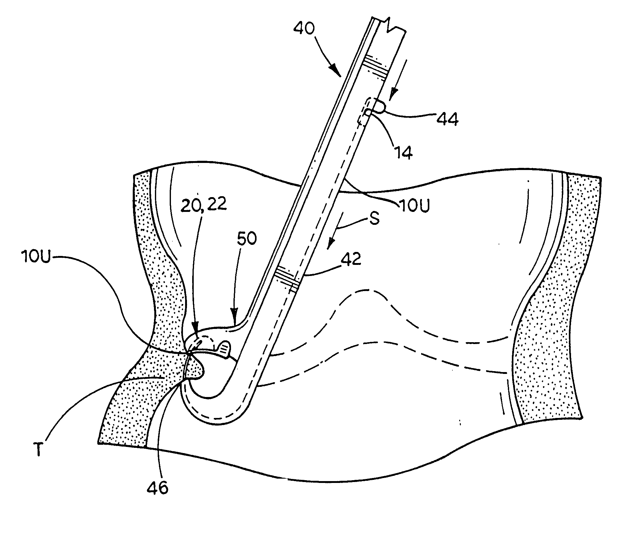
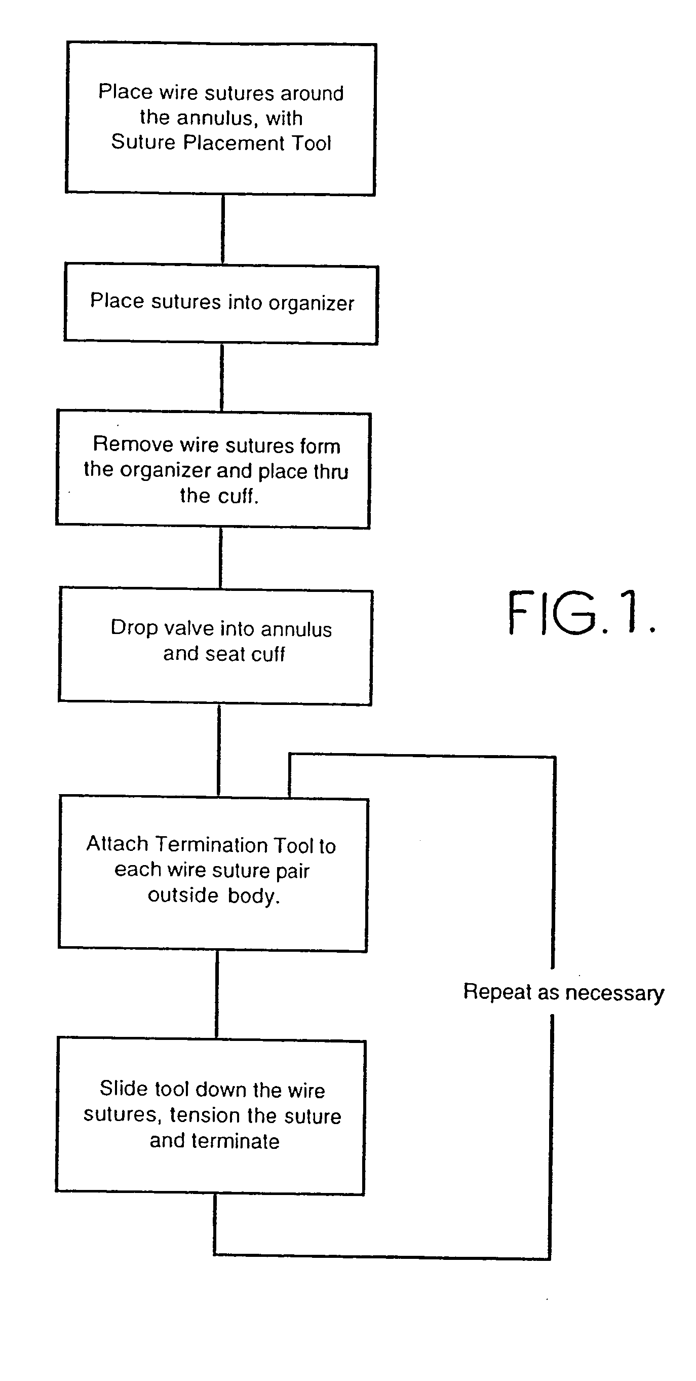
[0111] Referring first to FIG. 1 for a broad overview of the means and method embodying the present invention, it is seen that a minimally invasive procedure is carried out by, after defining the necessary incisions, etc., placing the long leg wire fasteners of the present invention, then organizing the legs of those fasteners since the legs are long enough whereby some portion of the legs is located outside the patient. A sewing cuff of the prosthesis to be placed in the patient is placed on the fastener legs and guided down the legs into place. The prosthetic device, such as a heart valve in the best mode description here, is also placed on the legs of the fasteners and guided down the legs into place next to the sewing cuff. This is a relatively easy process since the fastener legs guide the items directly to the target area. A tensioning and forming tool is then guided down the legs of each individual fastener and operated. Operation of the tensioning and forming tool first immo...


PUM


Abstract

Wire fasteners having legs with lengths that can be one hundred times the width of the fastener are used to secure items, such as prosthesis valves to a patient during minimally invasive surgery. The fasteners are manipulated into position and then are immobilized by means of the legs thereof for tensioning, cutting and forming in situ. The fasteners are manipulated, tensioned and formed from the leg end of the fasteners. Tools for initially placing the fasteners and for immobilizing, tensioning, cutting and bending the fastener legs are disclosed. Once the fasteners are initially placed, the prosthesis is placed on the long legs of the placed fasteners and is guided into position on the legs. Once the prosthesis is in position, the legs of the fasteners are immobilized, tensioned, cut and bent into staple-like shapes to secure the prosthesis to the patient. A method for carrying out the procedure using the long fastener is also disclosed. Using the teaching of the present disclosure, a surgeon can customize a fastener to the particular surgery or even to the particular portion of surgery being performed during the surgery.

Description

[0001] The present application is a continuation-in-part of Ser. No. 08 / 802,948 filed on Feb. 21, 1997 which is a continuation-in -part of Ser. No. 08 / 606,343 filed on Feb. 23, 1996. The disclosures of these applications are incorporated herein by reference.[0002] The present invention relates to the general art of minimally invasive surgery, and to the particular field of fasteners, tools and methods associated with minimally invasive surgery.[0003] In recent years, there has been a growing trend toward using minimally invasive surgical techniques to perform heretofore complicated and complex operations. Minimally invasive techniques have therefore been applied to many procedures such as gall bladder removal, operation on the reproductive organs, urological operations, and, more recently, heart valve repair and replacement as well as by-pass operations. Minimally invasive surgery uses only a small incision through which tools are inserted into the patient, with the tool being manip...

Claims


Application Information

Patent Timeline
Patent Type & Authority Applications(United States)
IPC IPC(8): A61B17/00A61B17/04A61B17/064A61B17/068A61B17/072A61B17/115A61B17/34A61B19/00A61F2/24
CPCA61B17/0401A61F2/2427A61B17/0469A61B17/0487A61B17/064A61B17/0644A61B17/0684A61B17/072A61B17/115A61B2017/00243A61B2017/0406A61B2017/0458A61B2017/0464A61B2017/047A61B2017/0641A61B2017/0725A61B2017/07271A61B2017/3486A61B2019/461A61B2019/545A61F2/2409A61B17/0467A61B2090/061A61B2090/395
Inventor WILLIAMSON, WARREN P. IVSPENCE, PAUL A.KELLER, GEORGE A.ROBINSON, CECIL R.WARD, THOMAS J.
Owner MEDTRONIC INC
Why Eureka
Try Eureka