
Method of detaching a thin film at moderate temperature after co-implantation

a technology of co-implantation and detachable films, which is applied in the direction of basic electric elements, semiconductor/solid-state device manufacturing, electric devices, etc., can solve the problems of affecting the crystalline quality of materials,

Active Publication Date: 2004-09-02
COMMISSARIAT A LENERGIE ATOMIQUE ET AUX ENERGIES ALTERNATIVES +1
View PDF49 Cites 69 Cited by
  • Summary
  • Abstract
  • Description
  • Claims
  • Application Information

AI Technical Summary

Benefits of technology

[0027] The invention is thus based on the implantation of two different species, characterized by different levels of efficacy to jointly form a weakened zone in the source substrate. One of the implanted species is chosen so as to localize the zone in which detachment will later occur by the formation of specific defects, the other is chosen to form a gas reservoir which will promote the extension of the specific defects designated previously, in particular by increasing their internal pressure.
[0028] Preferentially, the implantation of the first species, creating defects which promote detachment, is made firstly whereas the implantation of the other species, made so as to localize that second species in the zone of the defects created by the first species, is made secondly. This implantation order makes it possible to obtain a more favorable detachment dynamic.
[0029] In other words, implantation is advantageously carried out firstly of the first species, which has a high level of efficacy in creating a weakened layer (weakened is understood to mean the formation of specific defects of the micro-cavity and / or platelet etc. type), whereas, in this weakened layer, the second species, of lower efficacy in forming weakening defects, is implanted using a moderate dose. Being available in the weakened zone, the atoms of this second species will become trapped at or near the micro-cavities and / or platelets created at the time of the first implantation. At the time of the heat-treatment intended to induce detachment, the atoms of that second species will already be in place to participate in pressurizing the cavities present in the weakened layer and to enable their development; it follows from this that it is useful to choose as the second species a species having a high capacity to induce an effect of pressure in the cavities and / or micro-cracks located in the weakened layer. Nevertheless, it is possible to implant the second species first, which will later be available to progressively fill the defects which will be created by the implantation of the first species.
[0030] The first species is advantageously hydrogen (in one of its forms, for example in the form of H.sup.+ions), the modes of implantation of which are well known, but it should be understood that other species may be used. Furthermore, the second species is advantageously helium which makes it possible to efficaciously generate a pressurizing effect.
[0038] the first species is hydrogen, advantageously H.sup.+hydrogen, which is a species which can be easily implanted in numerous substrates, in silicon or another,
[0040] the second species is helium, which interacts in a particularly efficient manner with defects produced by an implantation of H.sup.+ions, and which efficaciously enables pressurization to be made of crystalline defects; the helium is advantageously implanted at a dose of the order of 1.times.10.sup.16 and 5.times.10.sup.16 atoms / cm.sup.2, which is a usual implantation dose in various substrates, and thus is easy to implement.

Problems solved by technology

These defects may be micro-bubbles and / or platelets and / or micro-cavities and / or dislocation loops and / or other crystalline defects, disrupting the crystalline quality of the material, of which the nature, the density and the size are strongly dependent on the species implanted as well as on the nature of the source substrate.
In this case, one of the major technological problems encountered is the presence of a field of very high stress in the various layers in contact, during the heat-treatment such as that during which the detachment of the thin film from the remainder of the source substrate occurs: this stress field is due to the difference in coefficients of thermal expansion between the various materials brought into contact.
This degradation may typically result in the breakage of one or both substrates brought into contact and / or in the substrates becoming unbonded at the bonding interface.
This approach, although reducing the thermal budget for detachment, uses an implantation at high dose which may represent a significant drawback from an industrial point of view (high cost).
Furthermore, it is of note that, due to the high implanted dose, the disrupted zone (comprising defects related to the implantation) at the surface of the transferred layer is thicker and the later processing operations necessary to eliminate that disrupted superficial zone may be more restrictive (greater removal of material, corresponding to more costly processing and potentially increasing the risks of lack of homogeneity of the thickness of the transferred layer).

Method used


Image

  • Method of detaching a thin film at moderate temperature after co-implantation
  • Method of detaching a thin film at moderate temperature after co-implantation

Examples


examples

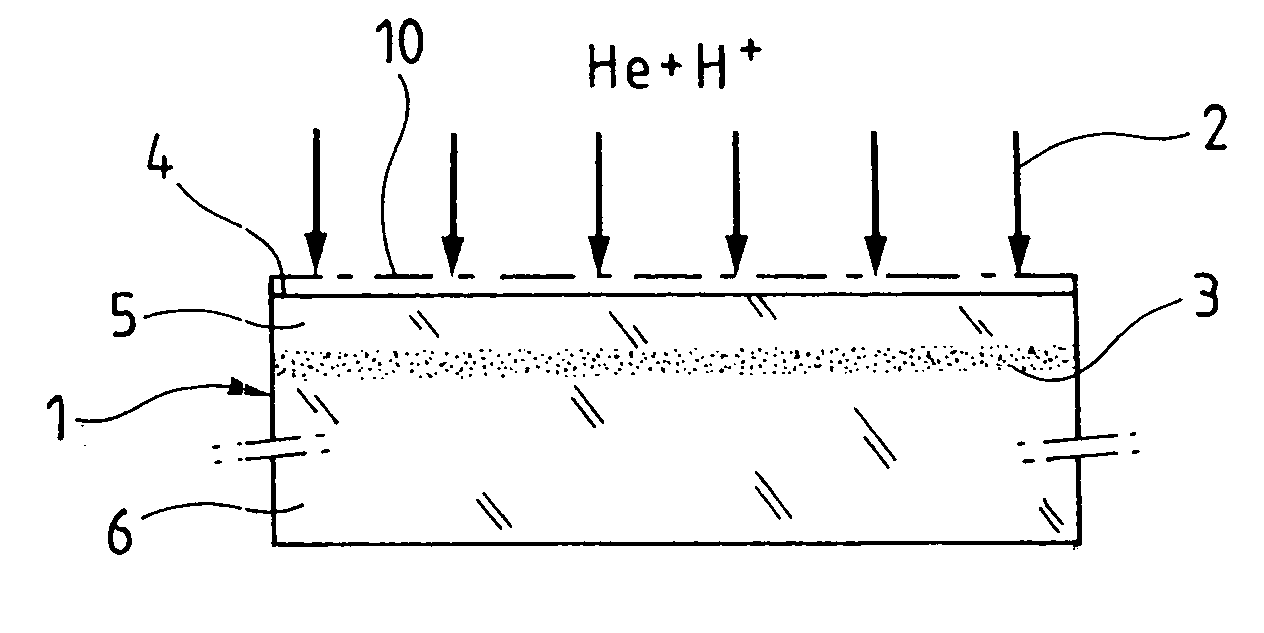
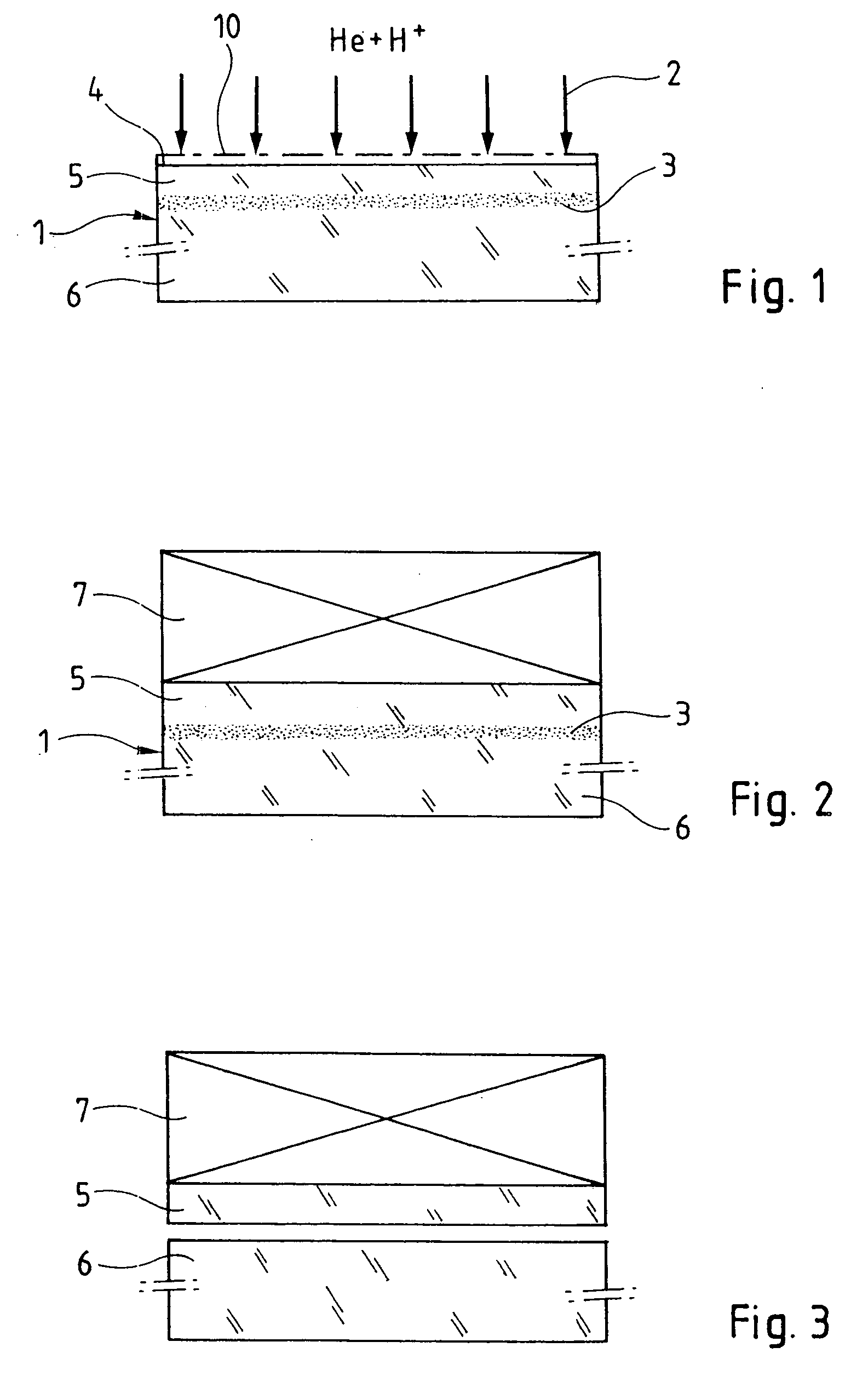
[0064] According to a first embodiment of the invention, a substrate of Si (.about.700 .mu.m) comprising a layer of thermal SiO.sub.2 on the surface (for example 200 nm) may be implanted initially with hydrogen atoms under implantation conditions of 30 keV-4.5.times.10.sup.16 H / cm.sup.2 and then be implanted with helium under the conditions of 45 keV-2.times.10.sup.16 He / cm.sup.2. This source substrate may next be joined to a target substrate of fused silica (.about.1000 .mu.m) by direct bonding. The difference that exists between the coefficients of thermal expansion of these two materials (2.56.times.10.sup.-6 / .degree.C. for silicon and

[0065] 0.5.times.10.sup.-6 / .degree.C. for fused silica, at ambient temperature) makes it necessary to perform a heat-treatment for detachment at low temperature, typically being around 250-300.degree. C. A heat-treatment around 275.degree. C. next induces the growth of the cavities localized at the peak hydrogen level, the helium atoms participating...


PUM


Abstract

A method of detaching a thin film from a source substrate comprises the following steps: implanting ions or gaseous species in the source substrate so as to form therein a buried zone weakened by the presence of defects; splitting in the weakened zone leading to the detachment of the thin film from the source substrate. Two species are implanted of which one is adapted to form defects and the other is adapted to occupy those defects, the detachment being made at a temperature lower than that for which detachment could be obtained with solely the dose of the first species.

Description

[0001] The present invention relates to a method of detaching a thin film from a substrate.[0002] It relates advantageously to the case of a transfer of that thin film from the substrate, referred to as source substrate, to a support referred to as target substrate, applicable in particular in the case where the target substrate is made from a different material to that of the source substrate (the term heterostructure is then used). This target substrate can just be an intermediate support from which the thin film will later be detached.[0003] Conventionally, the source substrate is fixed, for example, by molecular bonding, by one of its surfaces to the target substrate, then a thin film of the source substrate which extends along the target substrate is detached from the remainder of the source substrate, on which the procedure may then be iterated.[0004] The invention has applications in particular in the fields of micro-electronics, micro-mechanics, integrated optics and integra...

Claims


Application Information

Patent Timeline
IPC IPC(8): H01L21/30H01L21/301H01L21/46H01L21/762H01L21/78
CPCH01L21/76254
Inventor CAYREFOURCQ, IANMOHAMED, NADIA BENLAGAHE-BLANCHARD, CHRISTELLENGUYEN, NGUYET-PHUONG
Owner COMMISSARIAT A LENERGIE ATOMIQUE ET AUX ENERGIES ALTERNATIVES
Learn More