Discharging unit for discharging a photosensitive material, coater having the discharging unit, and apparatus for coating a photosensitive material having the coater

a technology of discharging unit and coating unit, which is applied in the direction of liquid surface applicators, instruments, photosensitive composition applications, etc., can solve the problems of process failure, thin film is insufficiently etched away during the etching process, and the spin coating process is disadvantageous to a heavy and broad substrate such as liquid crystal panels

Inactive Publication Date: 2004-09-09
SAMSUNG DISPLAY CO LTD
View PDF9 Cites 13 Cited by
  • Summary
  • Abstract
  • Description
  • Claims
  • Application Information

AI Technical Summary

Problems solved by technology

For example, when the photosensitive material is over-coated on the thin film, the photosensitive material on a portion of the thin film to be patterned is not completely removed, so that the thin film is insufficiently etched away during an etching process.
That is, when the photosensitive material is non-uniformly coated on a whole surface of the substrate, the thin film under the photosensitive material may be over-etched or under etched, finally causing process failures.
However, even though the photosensitive material is not uniformly coated on a light and small substrate such as a wafer for manufacturing semiconductor devices, the spin coating process is disadvantageous to a heavy and broad substrate such as a liquid crystal panel.
The broader and heavier the substrate is, the lower the angular speed is, and thus the photosensitive material is not uniformly coated on the substrate.
In addition, when the angular speed of the liquid crystal panel is increased for improving coating unifor

Method used


Image

  • Discharging unit for discharging a photosensitive material, coater having the discharging unit, and apparatus for coating a photosensitive material having the coater
  • Discharging unit for discharging a photosensitive material, coater having the discharging unit, and apparatus for coating a photosensitive material having the coater
  • Discharging unit for discharging a photosensitive material, coater having the discharging unit, and apparatus for coating a photosensitive material having the coater

Examples


embodiment 1

[0043] Embodiment 1

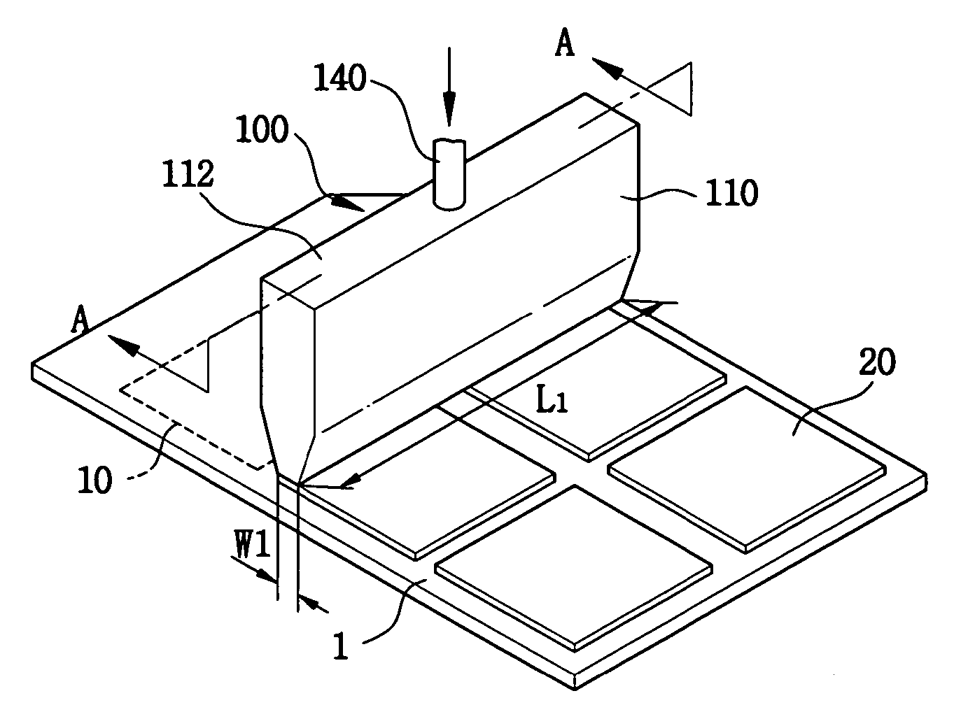
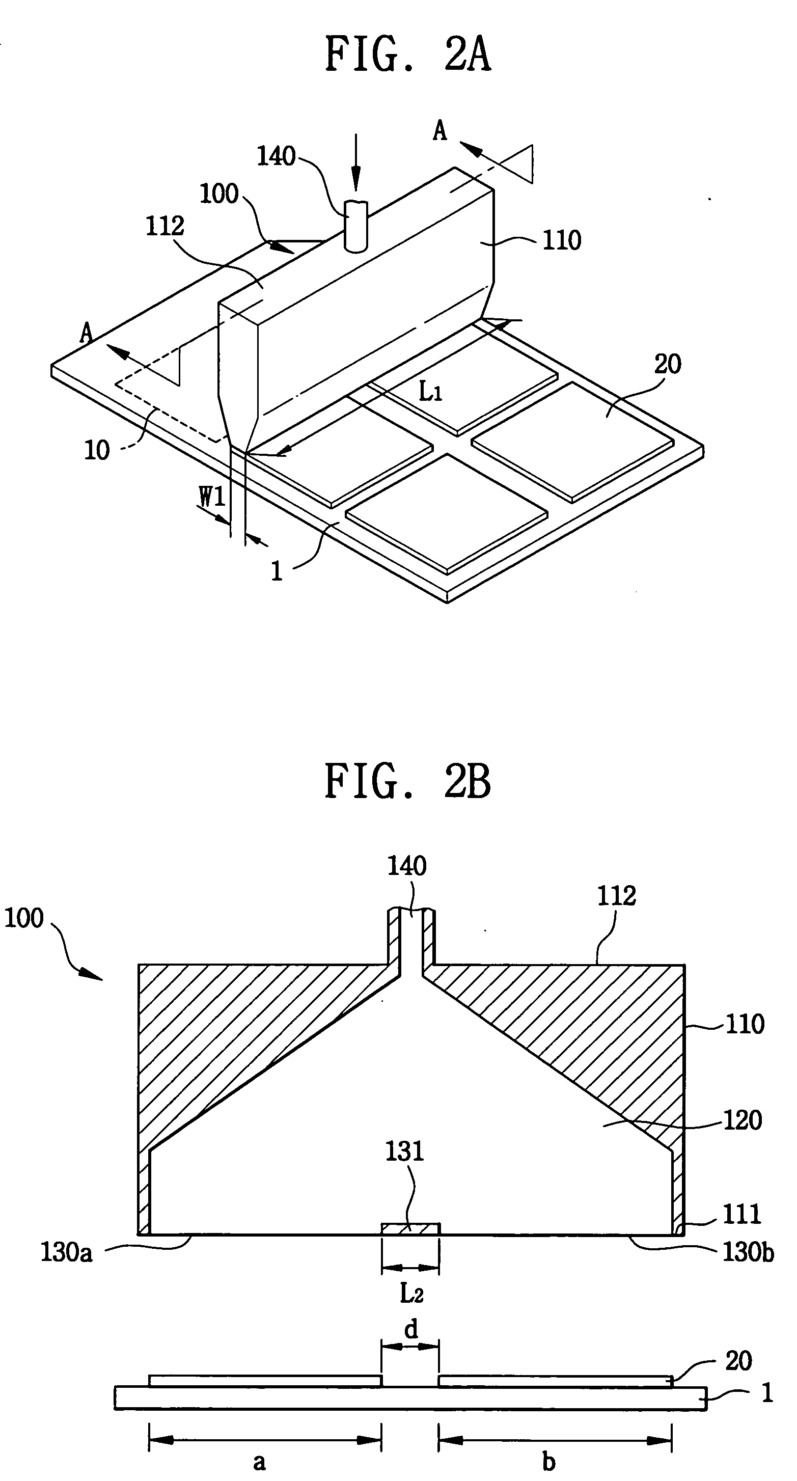
[0044] FIG. 2A is a perspective view showing a discharging unit for discharging a photosensitive material according to a first exemplary embodiment of the present invention. FIG. 2B is a cross-sectional view taken along the line A-A of FIG. 2A.

[0045] Referring to FIGS. 2A and 2B, a discharging unit 100 for discharging a photosensitive material includes a body 110 having a first face 111 facing a substrate 1 on which the photosensitive material is coated, an inlet portion 140 through which the photosensitive material is provided, and an outlet portion 130 through which the photosensitive material is discharged.

[0046] The body 110 includes a containing space 120 for containing the photosensitive material, a first face 111 facing the substrate 1, and a second face 112 opposite to the first face 111. The containing space 120 is formed inside the body 110 with a predetermined volume, and connected with an inlet portion 140 and an outlet portion 130. As an exemplary emb...

embodiment 2

[0057] Embodiment 2

[0058] FIG. 5A is a perspective view showing a discharging unit according to a second exemplary embodiment of the present invention. FIG. 5B is a cross-sectional view taken along the line B-B of FIG. 5A.

[0059] Referring to FIGS. 5A to 5B, a discharging unit 200 for discharging a photosensitive material includes a plurality of bodies 210 having a first face 211 facing a substrate 1 on which the photosensitive material is coated, an inlet portion 240 through which the photosensitive material is provided, an outlet portion 230 through which the photosensitive material is discharged, and at least a spacer block 250 for combining the bodies with each other.

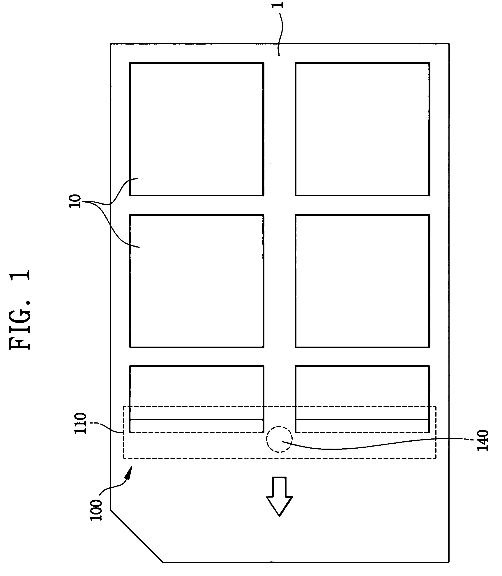
[0060] A plurality of unit substrates 10 and 20 for manufacturing an LCD panel is positioned on the mother substrate 1 that is spaced apart from each other by a predetermined distance d.

[0061] Each of the bodies 210 includes a containing space 220 for containing the photosensitive material, a first face 211 facing th...


PUM


Abstract

A coating apparatus includes support for supporting a mother substrate including unit substrates, a coater for coating the unit substrate with photosensitive materials, a detector for detecting foreign matters, a remover for removing the foreign matters from the unit substrate, and a controller for controlling the coater, detector, and remover. The coater includes a body containing the photosensitive materials, and inlet and outlet portions for inputting and outputting the photosensitive materials to/from the body. A width of the outlet portion is the same as that of the unit substrate. The detector is positioned at front of the coater to detect the foreign matters before the coating process. The remover removes the foreign matters. The coater discharges the photosensitive material only onto the unit substrate. Discharging of the photosensitive material is interrupted when the foreign matters are found. The coating apparatus requires less photosensitive material, and can be more efficient

Description

CROSS-REFERENCE OF RELATED APPLICATIONS[0001] This application claims priority under 35 USC .sctn. 119 to Korean Patent Application No. 2003-14016 filed on Mar. 6, 2003 and Korean Patent Application No. 2003-15009 filed on Mar. 11, 2003, the contents of which are herein incorporated by reference in their entireties.[0002] (a) Field of the Invention[0003] The present invention relates to a discharging unit, a coater having the discharging unit, and an apparatus for coating the photosensitive material. More particularly, the present invention relates to a discharging unit for discharging a photosensitive material, a coater including the discharging unit, and an apparatus for coating a photosensitive material using the coater, so that foreign matters are efficiently removed from a target wafer and the photosensitive material is selectively coated on the target wafer.[0004] (b) Description of the Related Art[0005] A photosensitive material, which may be chemically reactive to light, is ...

Claims


Application Information

Patent Timeline
IPC IPC(8): B05C5/02B05C9/10G03F7/16B05C11/00B05C11/10G02F1/13G03C1/74H01L21/027
CPCB05C5/0254G03C1/74B05C11/10B05C5/027B05C5/0208B05C11/1015
Inventor KIM, SEONG-BONGCHOI, DONG-UK
Owner SAMSUNG DISPLAY CO LTD
Why Eureka
Try Eureka