Filtering intensity decision method, moving picture encoding method, and moving picture decoding method

a decision method and intensity technology, applied in the direction of color televisions with bandwidth reduction, television systems, instruments, etc., can solve the problems of insufficient description of motion vectors to be used for comparison, insufficient decision algorithms in the prior art, and blocky artifacts usually occurring at decoded pictures of low bit rate video compression, etc., to achieve the effect of improving the quality of such moving pictures

Active Publication Date: 2004-09-16
GK BRIDGE 1
View PDF6 Cites 116 Cited by
  • Summary
  • Abstract
  • Description
  • Claims
  • Application Information

AI Technical Summary

Benefits of technology

0083] As described above, when the picture that includes the blocks p and q is a B picture, since a check is made to see if the number of reference pictures referred to by the block p and the number of reference pictures referred to by the block q are the same, and if reference picture(s) to be referred

Problems solved by technology

Blocky artifacts usually occur at decoded pictures of a low bit rate video compression due to quantization noise as well as motion compensation.
However, the decision algorithm in the prior art does not sufficiently cover all possible cases for blocks in a predicti

Method used


Image

  • Filtering intensity decision method, moving picture encoding method, and moving picture decoding method
  • Filtering intensity decision method, moving picture encoding method, and moving picture decoding method
  • Filtering intensity decision method, moving picture encoding method, and moving picture decoding method

Examples


second embodiment

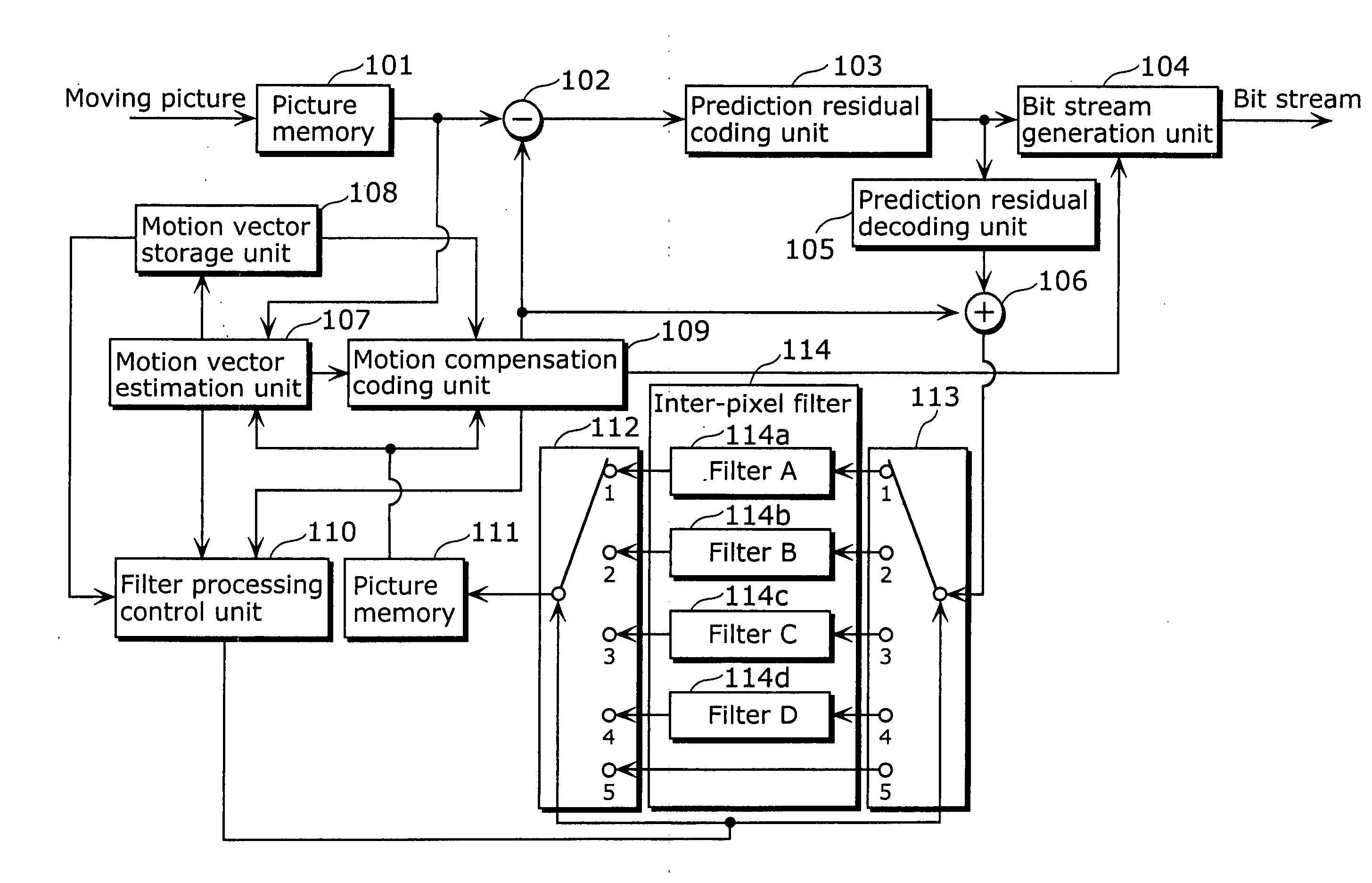
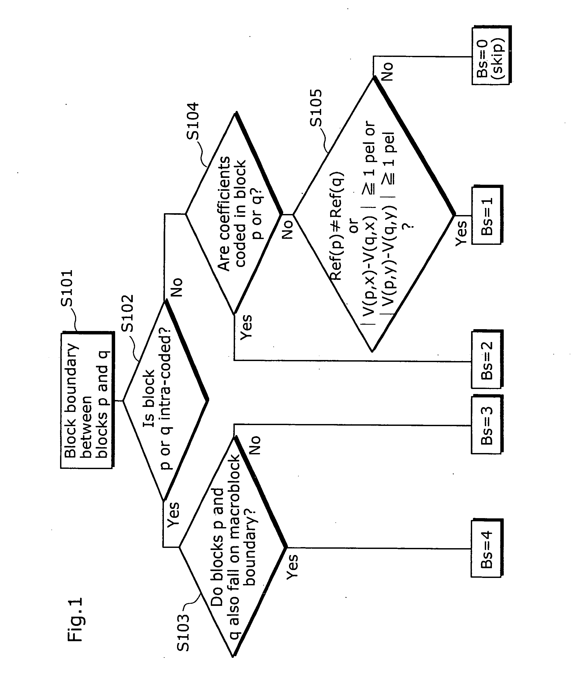
[0085] FIG. 8 is a flowchart illustrating a filtering strength determination method according to the

[0086] If the result of a check (Step S304) performed by the filter processing control unit 110 to see whether any of the two blocks p and q contains coefficients indicating spatial frequency components resulted from orthogonal transform, shows that one of these blocks contains coefficients (Yes in Step S304), the filter processing control unit 110 performs processing described below.

[0087] The filter processing control unit 110 checks to see if the picture that includes the blocks p and q is a P picture or a B picture (Step S311). If the picture that includes the blocks p and q is a P picture, the filter processing control unit 110 selects the filter C114c (Bs (p) .gtoreq.2) with the third strongest filtering strength. Meanwhile, if the picture that includes the blocks p and q is a B picture, the filter processing control unit 110 selects Bs (b) (Bs (b)>Bs (p)) with a stronger filter...

third embodiment

[0092] If a program for realizing the configuration of the moving picture coding method or the moving picture decoding method as shown in each of the aforementioned embodiments is recorded on a recording medium such as a flexible disk, it becomes possible to easily perform the processing presented in each of the aforementioned embodiments in an independent computer system.

[0093] FIG. 9 is a diagram explaining a recording medium which stores a program for realizing the moving picture coding method and the moving picture decoding method of the above embodiments in a computer system.

[0094] FIG. 9B shows an external view of the flexible disk viewed from the front, a schematic cross-sectional view and the flexible disk while FIG. 9A illustrates an example physical format of the flexible disk as a recording medium itself. A flexible disk FD is contained in a case F, a plurality of tracks Tr are formed concentrically on the surface of the disk in the radius direction from the periphery, an...


PUM


Abstract

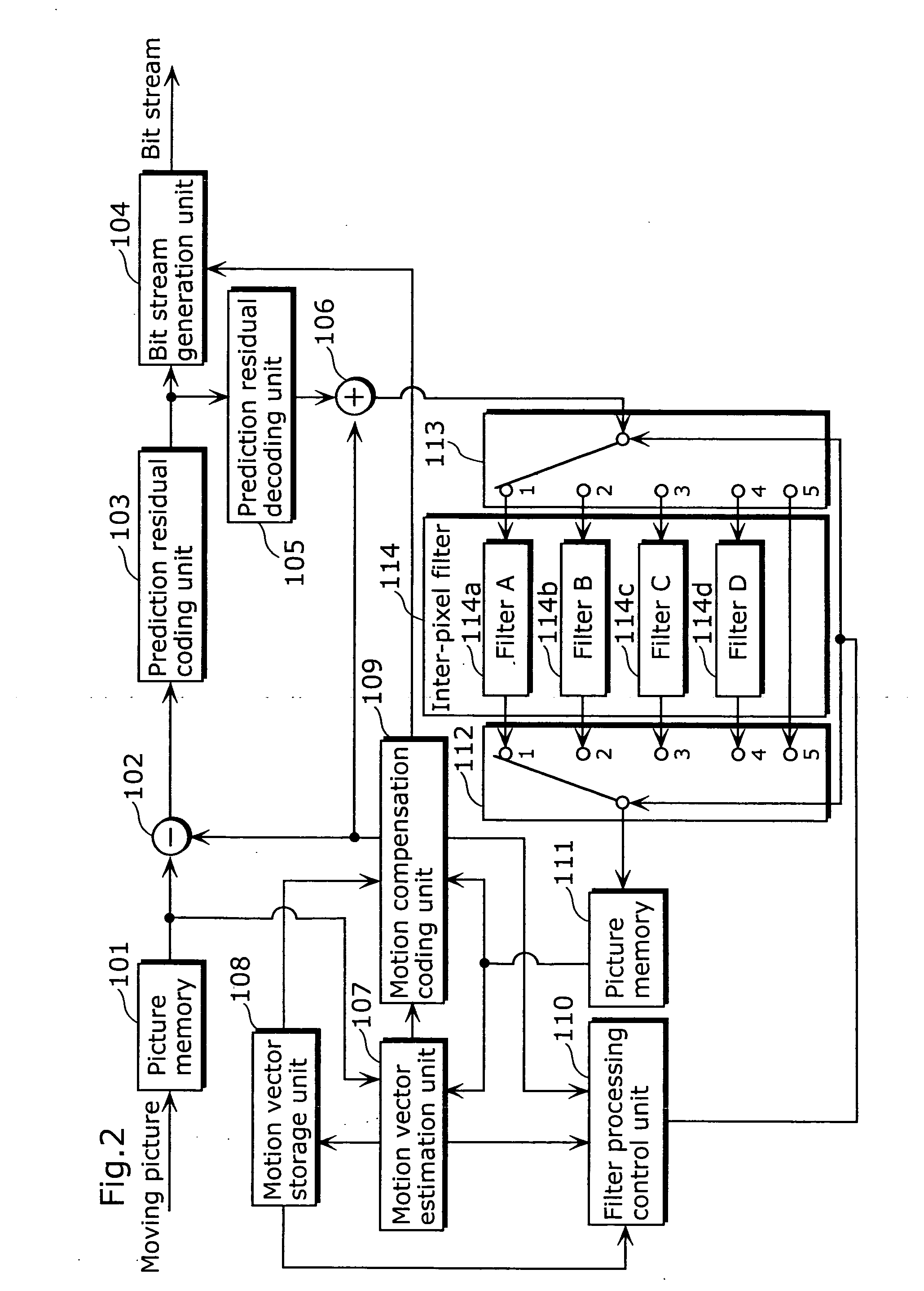
A moving picture coding apparatus includes (i) an inter-pixel filter (114) having the following filters for filtering decoded image data so as to remove block distortion which is high frequency noise around block boundaries: a filter A114a, a filter B114b, a filter C114c, a filter D114d, each having a different filtering strength, and (ii) a filter processing control unit (110) for determining a filtering strength of the inter-pixel filter (114).

Description

[0001] The present invention relates to a filtering strength determination method for determining a strength of filtering to remove inter-block coding distortion, as well as to a moving picture coding method and a moving picture decoding method for applying filtering with a determined strength so as to code / decode a moving picture.[0002] A filter is used in video compression technique usually to improve picture quality as well as compression ratio. Blocky artifacts usually occur at decoded pictures of a low bit rate video compression due to quantization noise as well as motion compensation. One of the tasks of a filter is to smoothen the boundaries of blocks in the decoded pictures so that these blocky artifacts are reduced or removed.[0003] Some video compression techniques, for example like the committee draft of ISO / IEC 14496-2 Part 10 which is under development, use loop filter to improve the compression of moving pictures (See Joint Video Team (JVT) of ISO / IEC MPEG and ITU-T VC...

Claims


Application Information

Patent Timeline
IPC IPC(8): H04N19/89G06T9/00H04N19/117H04N19/139H04N19/159H04N19/176H04N19/196H04N19/50H04N19/503H04N19/577H04N19/86
CPCH04N19/139H04N19/577H04N19/176H04N19/172H04N19/134H04N19/61H04N19/117H04N19/136H04N19/14H04N19/157H04N19/18H04N19/82H04N19/527H04N19/86H04N19/90H04N19/573H04N19/159H04N19/44H04N19/513H04N19/625H04N19/91
Inventor FOO, TECK WEELIM, CHONG SOONSHEN, SHENG MEIKADONO, SHINYA
Owner GK BRIDGE 1
Why Eureka
Try Eureka