Numerically controlled curved surface machining unit

a machining unit and numerical control technology, applied in the direction of electric programme control, program control, instruments, etc., can solve the problems of reducing the average feed rate by acceleration, affecting the smoothness of the machined surface, and requiring a lot of hand-finishing steps

Inactive Publication Date: 2004-09-16
HITACHI LTD +1
View PDF10 Cites 36 Cited by
  • Summary
  • Abstract
  • Description
  • Claims
  • Application Information

AI Technical Summary

Problems solved by technology

In conventional NC (numerically controlled) curved-surface machining, as shown in FIG. 10(a), it is machined by broken-line approximation, so that the machined surface roughness is bad and a lot of hand-finishing steps are needed thereafter.
However, even if in those conventional methods, there have been still left problems of reduction in machined surface roughness by the broken-line approximation and decrease in average feed rate by acceleration / deceleration when positioning.
However, any analysis about whether the sharp bend in tool control point behavior is caused by an operation due to NC data on the linear coordinate axes or operation on the rotary coordinate axis has not been conducted and there was no means for changing smoothly the two NURBS curves.
In the NC data by NURBS interpolation instruction, when a rotary axis rapidly reverses, stopping accuracy at a designated angle becomes bad by a rapid load change in a servo mechanism.
As a result, the tool control point 64 in a tool attitude 63 to be required at a reversing position of the rotary axis becomes really a tool control point 66 in a tool attitude 65 by a rapid load change of the servo mechanism, which results in worsening in cutting into the material to be machined and / or machined surface roughness, shortening in machine tool life, and excessive burden on the numerically controlled curved-surface machining unit.
When machining is carried out by sending angles formed in a conventional method to a controller of a machining unit without compensating or modifying, such a phenomenon that each axis rotates rapidly at a high speed, a tool moves to an unintended position, or the like occurs, whereby tool breakage, machining unit breakage, too much cutting or too less cutting occurs.

Method used


Image

  • Numerically controlled curved surface machining unit
  • Numerically controlled curved surface machining unit
  • Numerically controlled curved surface machining unit

Examples


first embodiment

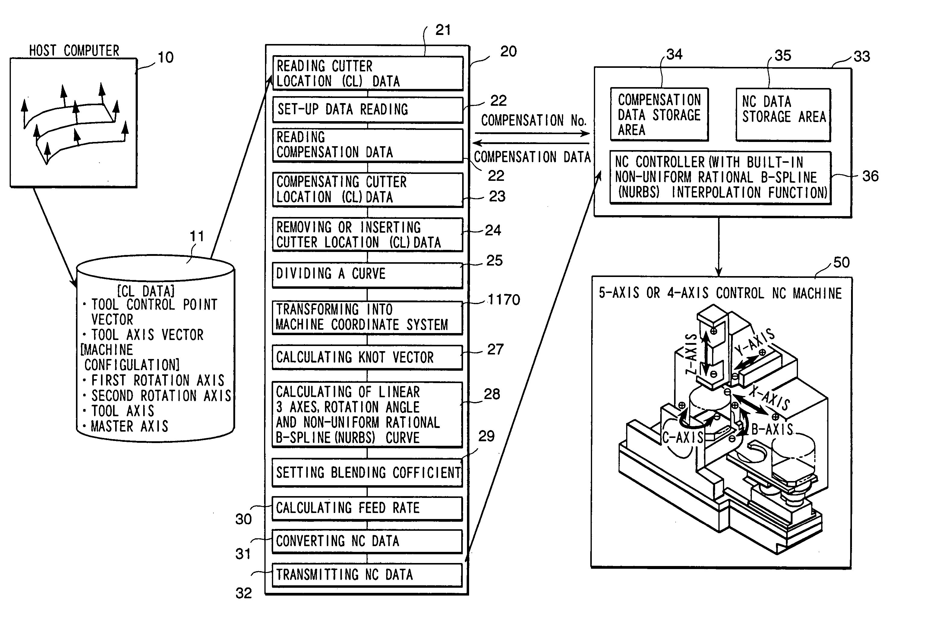
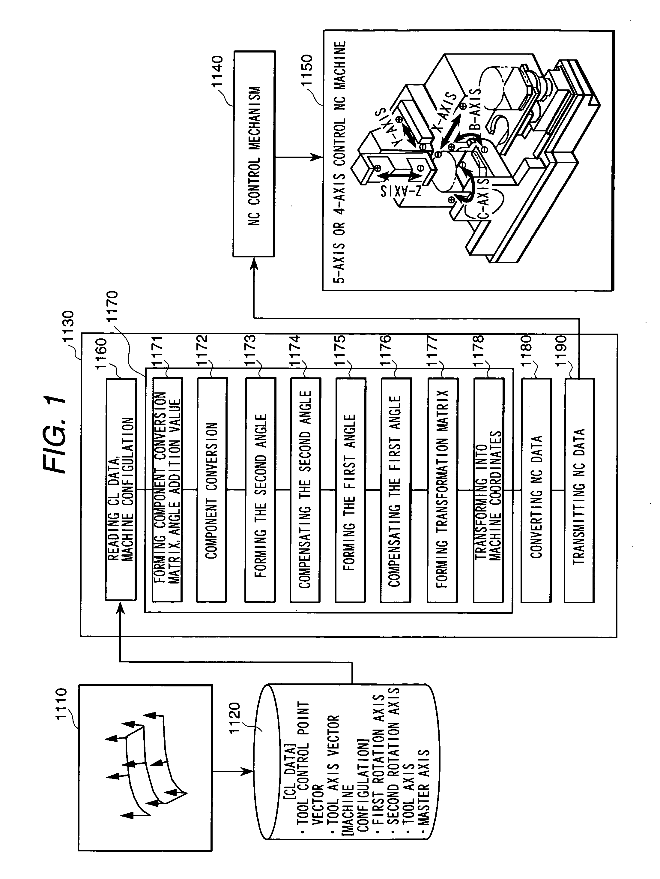
[0075] FIG. 1 shows the system configuration of a numerically controlled curved surface machining unit according to the present invention. More concretely, it show a configuration of NC host processor unit 1130 according to the present invention.

[0076] A CAM system 1110 working in a host computer uses CAD data of a finished shape defined by the CAD system, etc., forms CL (cutter location) data for a multi-axis controlled curved-surface machining unit 1150 (hereunder simply referred to as NC machine) and stores them in a CL data file 1120.

[0077] The CL data are composed of tool control point vectors (vectors of tool tip position, for example) and tool axis vectors (tool axis direction vectors, for example) and formed in a workpiece coordinate system defined by the CAM system. A configuration of the machine is expressed by character signs indicating a first rotary axis, second rotary axis, tool axis and master axis, of the NC machine 1150.

[0078] The NC post processor unit 1130 is comp...

embodiment 2

[0109] FIG. 5 is a block diagram showing a system configuration of a second embodiment of a numerically controlled curved surface machining unit according to the present invention.

[0110] The second embodiment is an embodiment in which the machine coordinate converting means of the numerically controlled curved-surface machining unit described in the previously mentioned US application or JP 2001-92516 is replaced by the coordinate converting means 1170 inside the post processor unit 1130 in FIG. 1.

[0111] Since the coordinate converting means 1170 can avoid a rapid change in angle by limit on computer installation, in the second embodiment also it is possible to prevent the phenomenon that each axis rapidly rotates at a high speed and the phenomenon that a tool moves to an unintended position and to perform such machining that tool breakage, machine breakage, too much cutting and too less cutting are less.

[0112] As for the means 1171 to 1190 of the machine coordinate converting means...


PUM


Abstract

A numerically controlled curved-surface machining unit comprises a component converting matrix.angle-addition value forming function of converting CL (cutter location) data into components on a normal coordinate system on the basis of the machine configuration of the simultaneous multiple-axis control NC machine, a component converting function of converting from the workpiece coordinate system to the normal coordinate system, a function of forming second angles of a second rotary axis on the normal coordinate system, a compensating function of forming a continuous angle distribution from a distribution of the second angles, a function of forming first angles of a first rotary axis on a coordinate system rotated by the second angles at the second rotary axis, a compensating function of forming a continuous angle distribution from a distribution of the first angles, a machine coordinate transformation matrix forming function of obtaining a matrix for converting the tool control point vectors on the workpiece coordinate system into a machine coordinate system by using the first angles and the second angles, and a machine coordinate converting function of converting the tool control point vectors into the machine coordinate system by using the machine coordinate transforming matrix.

Description

CROSS REFERENCE TO THE RELATED APPLICATION[0001] This is a Continuation-in-Part Application of U.S. patent application Ser. No. 10 / 437,279 filed May 14, 2003, which is now co-pending and a continuation application of U.S. patent application Ser. No. 09 / 791,561 filed Feb. 26, 2001, which is now patented as U.S. Pat. No. 6,587,747 B2, the subject matter of which is incorporated herein by reference.[0002] 1. Field of Utilization in Industry[0003] The present invention relates to a numerically controlled curved surface machining unit and, particularly to such a unit that improves machining surface roughness and accuracy and enables to achieve high-speed machining.[0004] 2. Description of Prior Art[0005] FIG. 10 shows comparison between a conventional linear interpolation machining method and a conventional NURBS interpolation machining method.[0006] In conventional NC (numerically controlled) curved-surface machining, as shown in FIG. 10(a), it is machined by broken-line approximation, ...

Claims


Application Information

Patent Timeline
Patent Type & Authority Applications(United States)
IPC IPC(8): G05B19/4099G05B19/4103
CPCG05B19/4099G05B2219/34141G05B19/4103
Inventor HIRAI, JUNICHIARAI, HIROSHIHARIHARA, TAMOTSUCHIBA, OSAMUTAKAHASHI, MASAAKIKANAMARU, NOBUHISA
Owner HITACHI LTD
Why Eureka
Try Eureka