Heat pump apparatus

a technology of heat pump and heat exchanger, which is applied in the direction of refrigeration machines, climate sustainability, compression machines with reversible cycles, etc., can solve the problems of many restrictions on conventional air conditioners, insufficient heating of lower-situated indoor units, and differences in installation height between indoor units, so as to improve the freedom of installation and reduce the pressure of the receiver 23

Inactive Publication Date: 2004-09-23
DAIKIN IND LTD
View PDF9 Cites 22 Cited by
  • Summary
  • Abstract
  • Description
  • Claims
  • Application Information

AI Technical Summary

Benefits of technology

[0015] The heat pump apparatus is provided with the communicating passageway (35) and the switching mechanism (36). The switching mechanism (36) is a mechanism capable of establishing and interrupting flow of gaseous refrigerant in the communicating passageway (35). When the switching mechanism (36) is open, gaseous refrigerant becomes circulatable in the communicating passageway (35), and gaseous refrigerant in the receiver (23) is delivered to the suction side of the compressor (41, 42). In other words, the compressor (41, 42) sucks in gaseous refrigerant from the receiver (23) and, as a result, the pressure of the receiver (23) decreases. On the other hand, when the switching mechanism (36) is closed, circulation of gaseous refrigerant in the communicating passageway (35) is prevented.
[0022] In accordance with the present invention, gaseous refrigerant is withdrawn from the receiver (23) in the heating operation, whereby the pressure of the receiver (23) is reduced. Stated another way, it is possible to gain, in the heating operation, a sufficient pressure difference between the inflow side of the heat source side circuit (20) and the outflow side of each of the utilization side circuits (60, 65), thereby ensuring that refrigerant condensed by each of the utilization side heat exchangers (61, 66) is delivered to the receiver (23).
[0023] As a result of such arrangement, even when the utilization side circuits (60, 65) are installed at different heights thereby producing a difference in installation height between the utilization side circuits (60, 65), it is ensured that refrigerant condensed by each of the utilization side heat exchangers (61, 66) flows into the receiver (23). Therefore it is possible to secure a sufficient flow rate of the refrigerant in each of the utilization side circuits (60, 65). Accordingly, in accordance with the present invention, it is possible to relax restrictions on the difference in installation height between the utilization side circuits (60, 65) at the time of installation of the heat pump apparatus, thereby improving the freedom of installation thereof.
[0024] Further, the present invention provides the following effects. These effects will be described below.
[0025] Liquid refrigerant and gaseous refrigerant coexist in the inside of the receiver (23). When the gaseous refrigerant is pumped out of the receiver (23) and, as a result, the pressure of the receiver (23) decreases, a part of the liquid refrigerant held in the receiver (23) is caused to evaporate, thereby robbing evaporation heat from the remaining liquid refrigerant. Consequently, the specific enthalpy of the liquid refrigerant held in the receiver (23) decreases. In other words, the specific enthalpy of the liquid refrigerant that is delivered from the receiver (23) to the heat source side heat exchanger (22) serving as an evaporator drops. Accordingly, it is possible to gain, by just that much, an enthalpy difference between the inlet and the outlet of the heat source side heat exchanger (22). As a result, it is possible to increase the refrigerant evaporation pressure in the heat source side heat exchanger (22) while securing the refrigerant heat absorption amount in the heat source side heat exchanger (22). As a result of this, the compression ratio of the compressor (41, 42) is reduced while maintaining the amount of heat liberation in the utilization side heat exchangers (61, 66), and it becomes possible to improve the COP (coefficient of performance) of heat pump apparatus.

Problems solved by technology

Installation of a multi type airconditioner in a building may result in a difference in installation height between indoor units.
However, if the difference in installation height between the indoor units becomes greater, this causes the problem that the refrigerant flows only through the upper-situated indoor unit, in other words no refrigerant flows in the lower-situated indoor unit during the heating mode of operation of the airconditioner.
As a result, the lower-situated indoor unit fails to provide sufficient heating.
Consequently, conventional airconditioners are subject to many restrictions on the difference in installation height between indoor units and the degree of layout freedom at the time of installation in a building is little.
However, even when the indoor expansion valve of the second indoor unit (13) is fully opened, it is impossible to reduce the differential pressure .DELTA.P.sub.i2 to zero.

Method used


Image

  • Heat pump apparatus
  • Heat pump apparatus
  • Heat pump apparatus

Examples


modification examples

[0075] Modification Examples of Present Embodiment

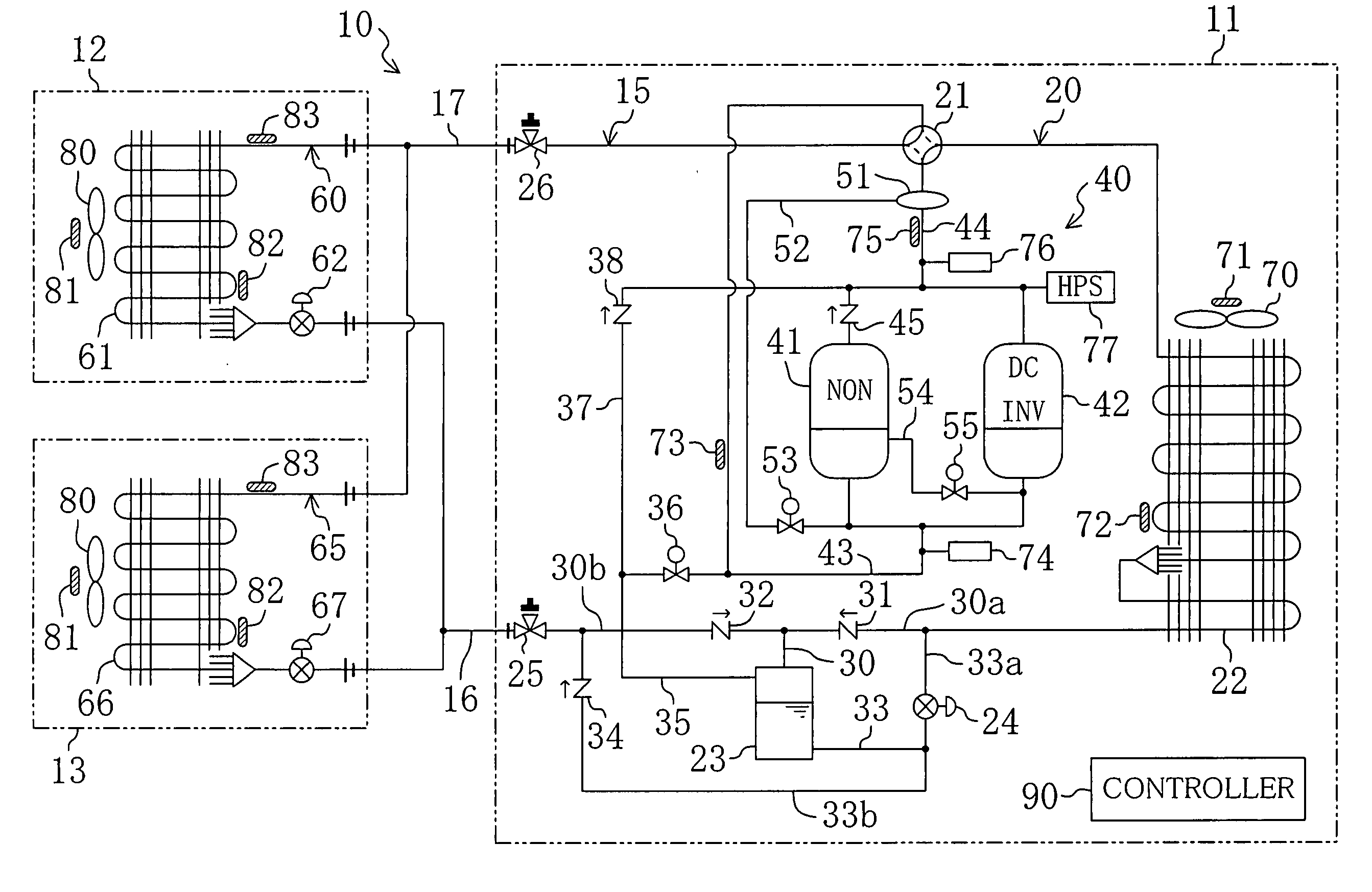
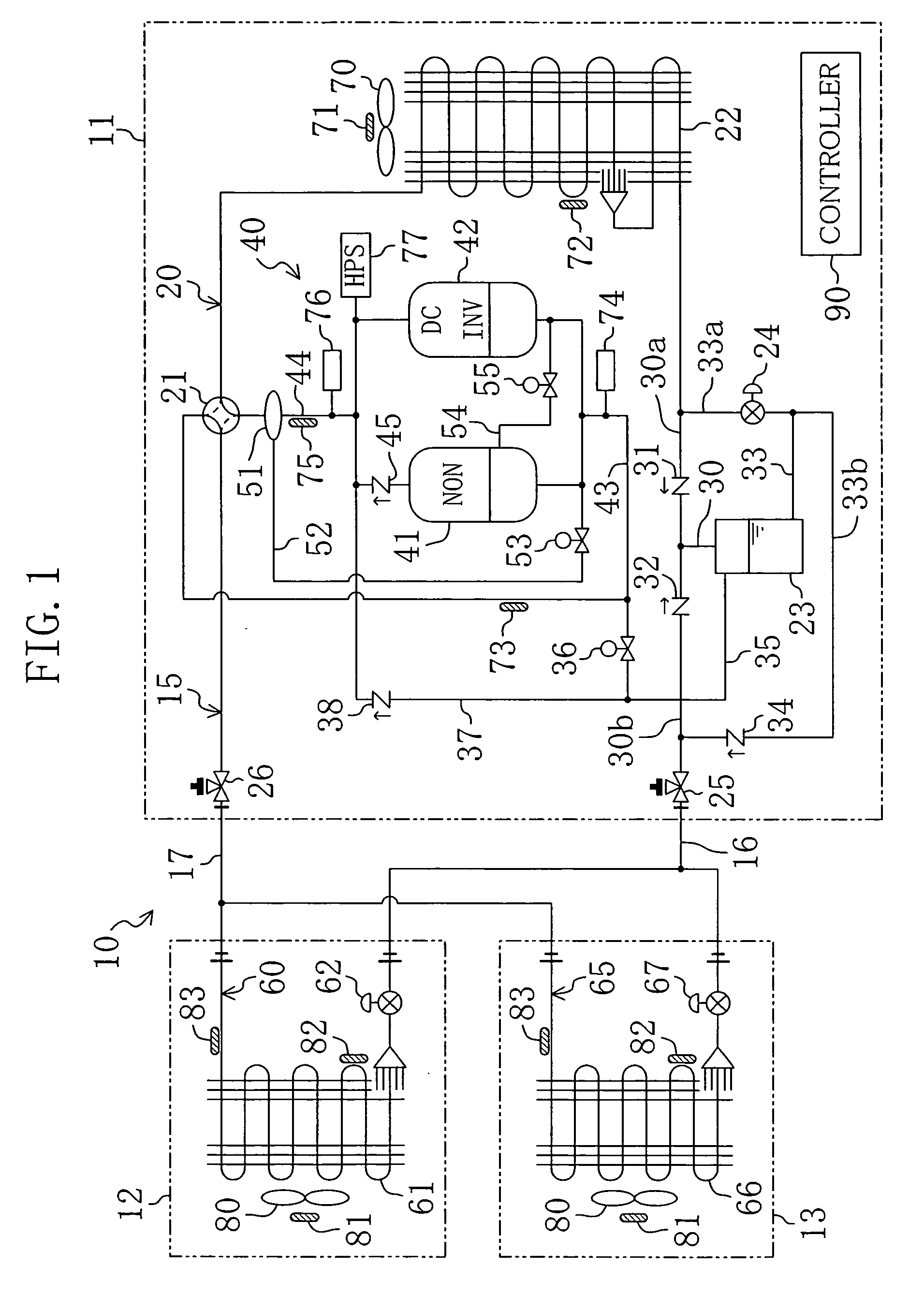
[0076] In the present embodiment, the controller (90) controls the gas vent solenoid valve (36) in the heating mode of operation and the gas vent solenoid valve (36) is held constantly in the open state during the heating operation. Alternatively, it may be arranged such that, even during the heating operation, the gas vent solenoid valve (36) is placed in the open state only when predetermined conditions are met.

[0077] More specifically, it may be arranged such that the receiver (23) is depressurized by placing the gas vent solenoid valve (36) in the open state when the second indoor expansion valve (67) is fully opened during the heating operation in the heating mode of operation. In other words, when the second indoor expansion valve (67) is fully opened, it becomes impossible to gain any more pressure difference between the outflow side of the second indoor circuit (65) and the outdoor circuit (20). Consequently, the flow rate of...


PUM


Abstract

Indoor circuits (60, 65) of indoor units (12, 13) are each connected in parallel to an outdoor circuit (20) of an outdoor unit (11). The outdoor circuit (20) has a gas vent pipe (35) by which a receiver (23) is brought into communication with suction sides of compressors (41, 42). During the heating operation in the heating mode of operation, a gas vent solenoid valve (36) is placed in the open state so that the receiver (23) decreases in pressure. This relaxes restrictions on the difference in installation height between each indoor unit of a multi type airconditioner having a plurality of indoor units.

Description

TECHNICAL FIELD OF INVENTION[0001] The present invention relates to a heat pump apparatus which performs a refrigeration cycle.BACKGROUND OF INVENTION[0002] Airconditioners of the so-called multi type have been known in the prior art. Japanese Patent Kokai Gazette No. (1998)300292 discloses one such airconditioner that includes a single outdoor unit and a plurality of indoor units connected to the outdoor unit. In this airconditioner, the outdoor unit contains an outdoor circuit and each indoor unit contains an indoor circuit. The outdoor circuit of the outdoor unit includes a compressor, an outdoor heat exchanger, an outdoor expansion valve, a receiver, et cetera. On the other hand, the indoor circuit of each indoor unit includes an indoor heat exchanger and an indoor expansion valve. The indoor units are each connected in parallel to the outdoor unit to form a refrigerant circuit of the airconditioner.[0003] The above-described airconditioner performs a refrigeration cycle by circ...

Claims


Application Information

Patent Timeline
Patent Type & Authority Applications(United States)
IPC IPC(8): F25B13/00
CPCF25B13/00F25B2313/02331F25B2313/02334F25B2400/0751F25B2600/2513F25B2500/01F25B2600/021Y02B30/741F25B2313/005F25B2400/16Y02B30/70
Inventor SHIMODA, JUNICHIMATSUOKA, HIROMUNE
Owner DAIKIN IND LTD
Why Eureka
Try Eureka