Sensorless control of switched reluctance electric machines

a technology of switched reluctance electric machines and sensorless control, which is applied in the direction of dynamo-electric converter control, motor/generator/converter stopper, dynamo-electric gear control, etc., which can solve the problems of reducing reliability, and adding cost and complexity to the overall drive system

Inactive Publication Date: 2004-09-30
GM GLOBAL TECH OPERATIONS LLC +2
View PDF5 Cites 30 Cited by
  • Summary
  • Abstract
  • Description
  • Claims
  • Application Information

AI Technical Summary

Benefits of technology

0004] Disclosed herein is a method for sensorless control of a switched reluctance electric machine comprising: probing a selected diagnostic phase of a switched reluctance electric machine with a pulse injection process; measuring an actual operating characteristic of the switched reluctance electric machine; computing an inductance based on the actual operating characteristic and correlating the inductance with a position to formulate an estimated position; modeling the switched reluctance electric machine to formulate a modeled position; selecting at least one of the estimated position, the modeled position, or a combination thereof to formulate a selected position of the switched reluctance machine; controlling the switched reluctance machine based on the selected position and a desired command.

Problems solved by technology

The position information for a SRM drive is usually, obtained from a position sensor, often a shaft-mounted encoder or resolver, which adds cost and complexity to the overall drive system.
Use of discrete position sensors adds cost and complexity to the overall drive system and generally reduces reliability especially in harsh environments.

Method used


Image

  • Sensorless control of switched reluctance electric machines
  • Sensorless control of switched reluctance electric machines
  • Sensorless control of switched reluctance electric machines

Examples


Embodiment Construction

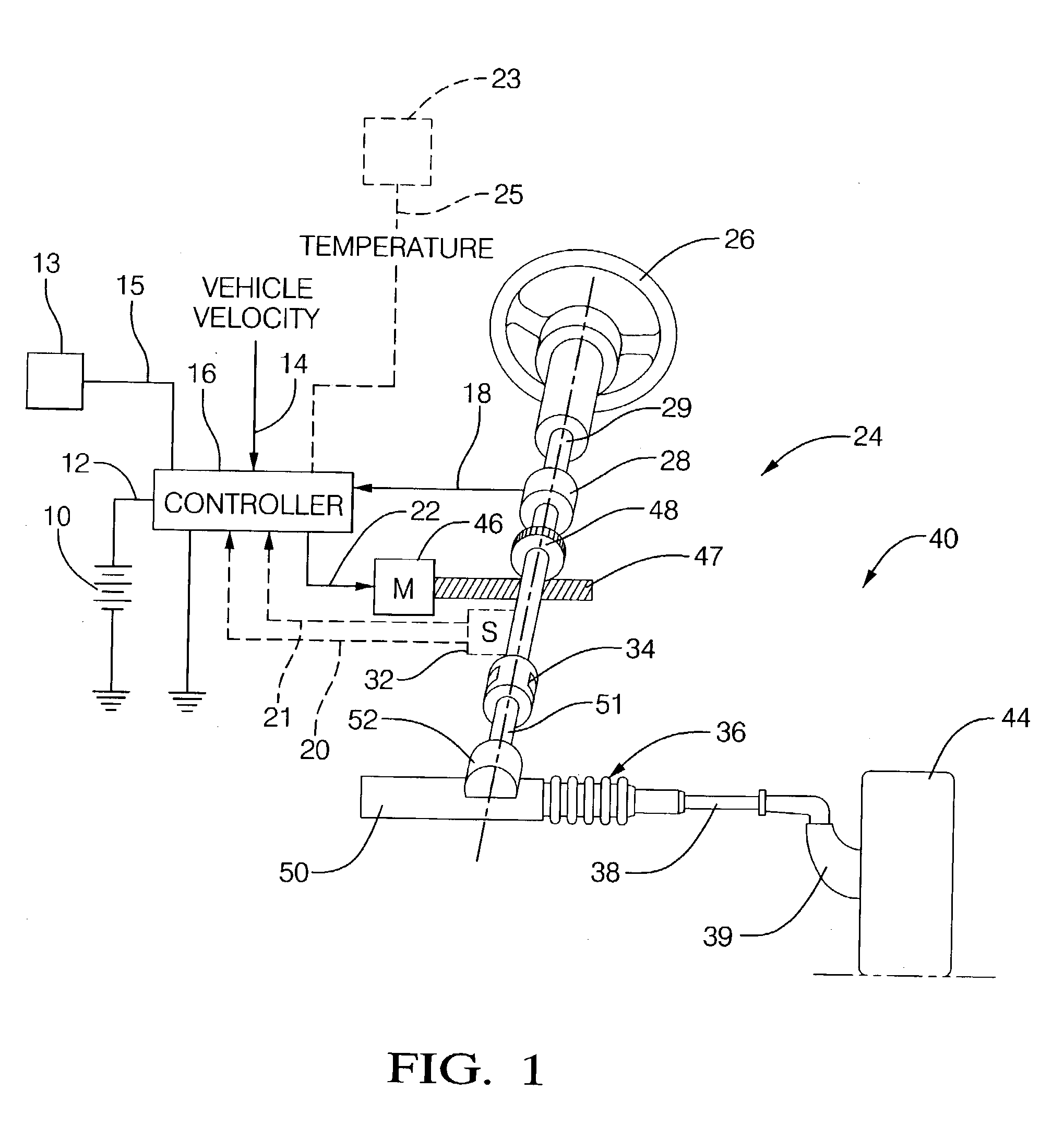
[0016] Referring to FIG. 1, reference numeral 40 generally designates a motor vehicle electric power steering system suitable for implementation of the disclosed embodiments. The steering mechanism 36 is a rack-and-pinion type system and includes a toothed rack (not shown) within housing 50 and a pinion gear (also not shown) located under gear housing 52. As the operator input, hereinafter denoted as a steering wheel 26 (e.g. a hand wheel and the like) is turned, the upper steering shaft 29 turns and the lower steering shaft 51, connected to the upper steering shaft 29 through universal joint 34, turns the pinion gear. Rotation of the pinion gear moves the rack, which moves tie rods 38 (only one shown) in turn moving the steering knuckles 39 (only one shown), which turn a steerable wheel(s) 44 (only one shown).

[0017] Electric power steering assist is provided through the control apparatus generally designated by reference numeral 24 and includes the controller 16 and an electric mac...


PUM


Abstract

A system and methodology for control of a switched reluctance electric machine comprising: a switched reluctance electric machine including a sensor generating and transmitting a sensor signal indicative of an operating characteristic; a controller operatively coupled to the switched reluctance motor and the sensor; and the controller executing a method. The method comprises: probing a selected diagnostic phase with a pulse injection process; measuring an actual operating characteristic of the switched reluctance electric machine; computing an inductance based on the actual operating characteristic and correlating the inductance with a position to formulate an estimated position; modeling the switched reluctance electric machine to formulate an observer-based estimated position; selecting at one of the estimated position, the observer-based estimated position, and a combination thereof to formulate a selected position of the switched reluctance machine; and controlling said switched reluctance machine based on said selected position and a command.

Description

[0001] This invention relates to sensorless operation of a switched reluctance electric machine.[0002] A switched reluctance motor (SRM) is a viable candidate for various motor control applications due to its rugged and robust construction. A high-performance SRM drive is possible by appropriately scheduling the commutation angles using accurate rotor position and speed information. The position information for a SRM drive is usually, obtained from a position sensor, often a shaft-mounted encoder or resolver, which adds cost and complexity to the overall drive system.[0003] Sensorless operation is a key feature required to make SRM drives industrially competitive. Sensorless operation is important for various applications due to the need for minimum package size, high reliability and low cost for electric motor driven actuators. Use of discrete position sensors adds cost and complexity to the overall drive system and generally reduces reliability especially in harsh environments. Re...

Claims


Application Information

Patent Timeline
Patent Type & Authority Applications(United States)
IPC IPC(8): H02P25/08
CPCH02P25/083H02P25/089
Inventor ISLAM, MOHAMMAD S.MIR, SAYEED A.SEBASTIAN, TOMYHUSAIN, IQBAL
Owner GM GLOBAL TECH OPERATIONS LLC
Why Eureka
Try Eureka