Drying method and drying apparatus for coating layer

a drying apparatus and coating layer technology, which is applied in the direction of lighting and heating apparatus, drying machines with progressive movements, furnaces, etc., can solve the problems of uneven thickness of coating layer, unevenness or mura generation, and poor conditions of coating layer

Inactive Publication Date: 2004-09-30
FUJIFILM CORP +1
View PDF39 Cites 21 Cited by
  • Summary
  • Abstract
  • Description
  • Claims
  • Application Information

AI Technical Summary

Problems solved by technology

Although the blow-drying method is excellent in the drying efficiency, the wind is blown to the coating layer directly or through a porous plate, straightening plate, or the like, which causes the bad conditions for the coating layer.
Accordingly, the thickness of the coating layer loses uniformity, and unevenness or mura is generated.
Further, the convection of the wind makes the evaporation speed of the solvent from the coating layer on coating surface nonuniform.
Especially when an organic solvent is contained in a coating solution, the unevenness is generated so much.
The generation of the unevenness is a considerable coating defect.
Further, when the liquid crystal compounds are contained in the coating layer, it is hard to obtain the predetermined and uniform orientation by blowing the wind to the substrate.
However, as described in Japanese Patent Laid-Open Publication No. 2001-170547 (Page 3-5, FIG. 1), the above two methods are not adequate for the high speed coating, and increase the drying time, which causes the extremely low productivity.
When a drying apparatus which has a casing surrounding the web is

Method used


Image

  • Drying method and drying apparatus for coating layer
  • Drying method and drying apparatus for coating layer
  • Drying method and drying apparatus for coating layer

Examples


Embodiment Construction

[0030] In the present invention, it is preferable that a blow-drying apparatus is provided after a drying apparatus. In this case, when much solvent (especially organic solvent) remains in the solution cast on a web, the drying unevenness easily generated. Therefore, in the present invention, the coating solution contains preferably at least 50% by mass.

[0031] Further, the effect of the present invention is very effective, when the organic solvent is contained in the coating solution, otherwise when only one or more organic solvent is used as a solvent of the coating solution. Furthermore, the effect of the present invention is more effective, when the boiling point of the organic solvent is low.

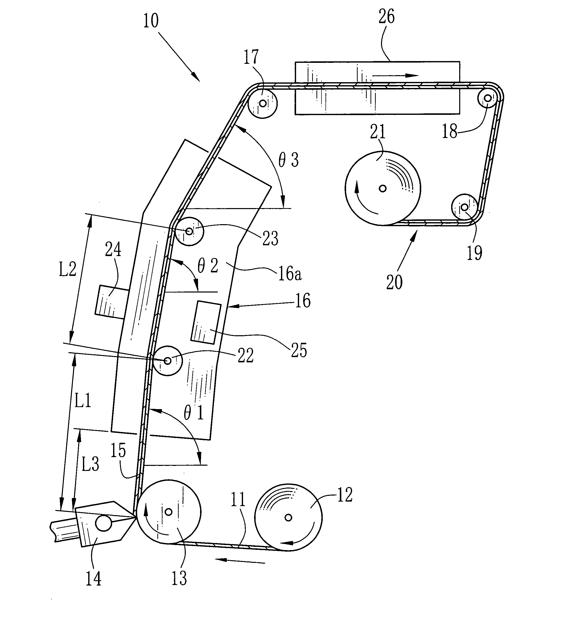
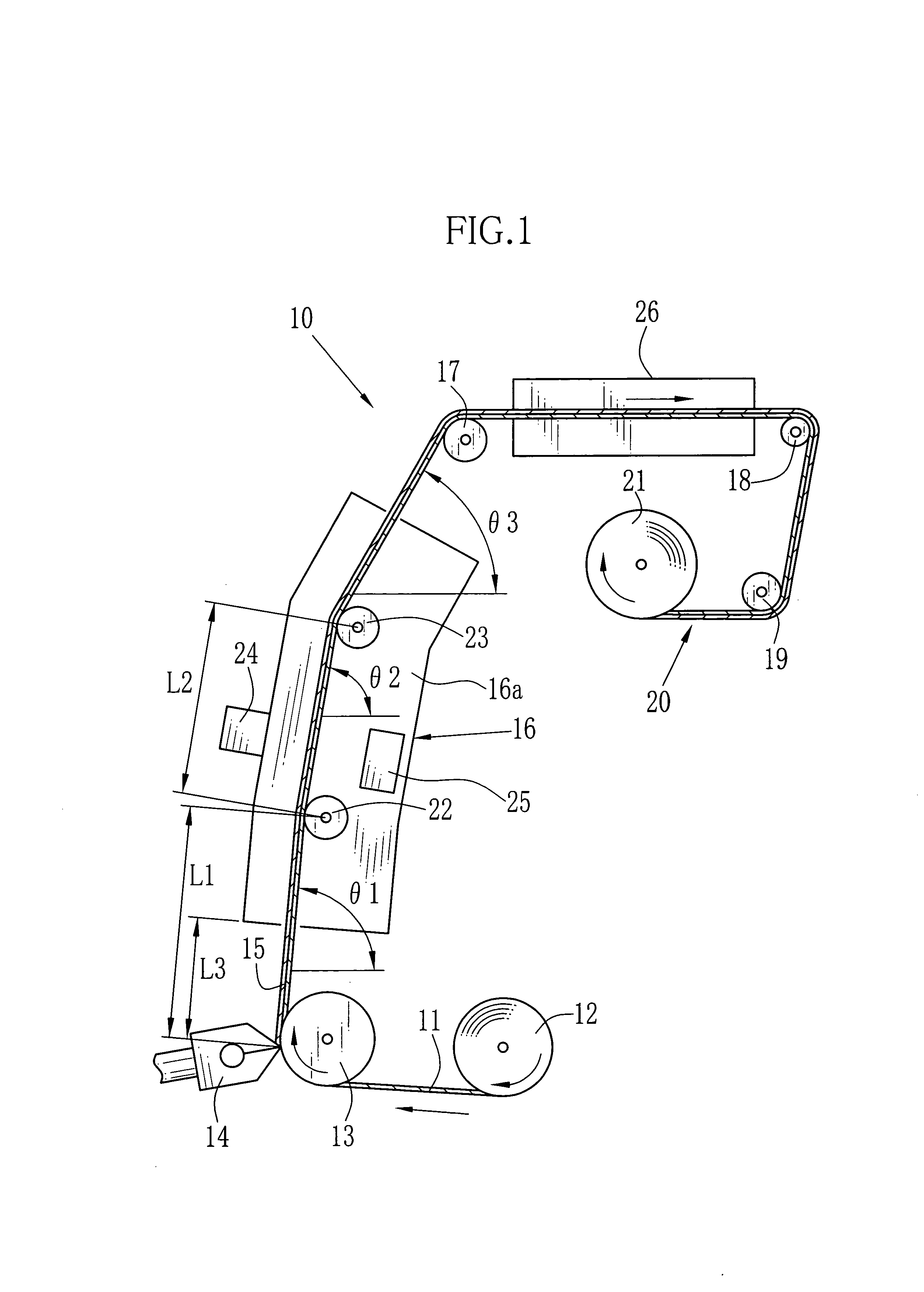
[0032] In FIG. 1, a coating / drying line 10 has a feeding apparatus 12, a back-up roller 13, an extrusion die 14, a drying apparatus 16, rollers 17-19, and a winding apparatus 21. The feeding apparatus 12 unwinds and feeds a web 11 wound in a web roll. The back-up roller 13 confront to the ex...


PUM


Abstract

A coating solution is applied to a web to form a coating layer. Then the web is transported into a drying apparatus, in which a guide roller guides the web such that an angle of the web to a horizontal direction is smaller downstream from the guide roller. The angles at entrance and exit of the drying apparatus are named entrance and exit angles theta1, theta3, respectively, and satisfy a condition theta1>theta3. The coating layer has the temperature T1 at the entrance, the temperature T2 at the exit, and the temperature T3 in the drying apparatus. The differences |T2-T1| and |T3-T1| are at most 5° C. In the drying apparatus, as the organic solvent evaporates uniformly, the generation of the unevenness is reduced. Thereafter, the drying is made at the large drying speed in the blow-drying apparatus to obtain a film product.

Description

[0001] 1. Field of the Invention[0002] The present invention relates to a drying method and a drying apparatus for drying a coating layer, and particularly to a drying method and a drying apparatus for drying a coating layer on a continuous and wide coating surface of a web as a continuously running flexible substrate while at least one liquid composition is applied on the web so as to form the coating layer.[0003] 2. Description Related to the Prior Art[0004] E. B. Gutoff & E. D. Cohen teaches in the publication "Coating and Drying Defects" (Wiley-Interscience, John Wiley & sons, Inc) some methods and apparatuses for drying a wet coating layer on a continuous and wide coating surface of a web as a continuously running flexible substrate while at least one liquid composition is applied onto the web so as to form the coating layer. In the method and apparatus for drying, an wind is blown from an air nozzle to dry a wet coating layer on a coating surface of the web while another non-c...

Claims


Application Information

Patent Timeline
IPC IPC(8): F26B3/28F26B13/10F26B13/18F26B23/10F26B25/00
CPCF26B13/10F26B25/006F26B13/18
Inventor OKI, KAZUHIROKITAOKA, TAKESHI
Owner FUJIFILM CORP
Why Eureka
Try Eureka