Sealing device

a sealing device and sealing technology, applied in the field of sealing devices, can solve the problems of high noise development, clearly audible, shrill, and the effect of "suction roll whistle"

Inactive Publication Date: 2004-10-07
VOITH PATENT GMBH
View PDF17 Cites 4 Cited by
  • Summary
  • Abstract
  • Description
  • Claims
  • Application Information

AI Technical Summary

Benefits of technology

[0012] The rear ventilation section can be composed of the same material as the front sealing section and preferably can be made in one piece. In accordance with an advantageous alternative embodiment, the ventilation section can, however, be composed of a different material than that of the sealing section and, preferably, these two sections can be made separately from each other and secured together. The ventilating section can advantageously be composed a porous sound-absorbing plastic, whereby the noise level is even further reduced.
[0015] Due to this design, the openings provided in the respective moved surface are not exposed abruptly, but continuously, so that a continuous pressure compensation or pressure reduction takes place in these openings. Accordingly, the noise development is reduced to a minimum or even completely eliminated. In the case of a suction roll, the occurrence of the so-called "suction roll whistling" is at least reduced. Moreover, an advantage results with respect to the previously recited solution with teeth of an even clearer noise reduction at higher speeds. In contrast to the toothed version or crest version, a ventilation of suction openings or suction orifices occurs, e.g., over the total width in the present case so that lacks in constancy are excluded in the reduction of the vacuum.
[0020] It is also of advantage for the gap to expand in the running direction of the moved surface. The gap can thus be kept relatively narrow, with it nevertheless being ensured that the sealing edge which is at the rear considered in the running direction is substantially offset from the moved surface. The sealing element can, for example, have a reducing thickness in the running direction of the moved surface.
[0024] It is also of advantage for the pressure device to be arranged at the side of the sealing element remote from the moved surface. The sealing element can, e.g., including a lug that preferably extends in the pivot direction, with the lug being exposed to action by the pressure device.
[0051] Further, the sealing element can include a groove, and the sealing device may further include a pivot bearing arranged to pivotably mount the sealing element. The pivot bearing may include a fixed bearing element arranged to engage the groove. The groove can be arranged at a rear end face located at the rear, and the sealing device may further include a fixed guide surface arranged in a region of a front end face of the sealing element. The fixed guide surface may be structured and arranged to permit the pivoting movement of the sealing element and to prevent the sealing element from moving away from the fixed bearing element, thereby maintaining the pivot bearing. The front end face can have a curved surface. Further, the fixed guide surface can be planar, or the fixed guide surface may be curved.
[0053] In accordance with another feature, the sealing element may have a reducing thickness in the running direction.

Problems solved by technology

However, the vacuum in the roll perforation breaks down abruptly at such a runoff edge of the sealing strip running off in the wire travel direction, which produces an extremely high development of noise and results in a clearly audible, shrill so-called "suction roll whistle".

Method used


Image

  • Sealing device
  • Sealing device
  • Sealing device

Examples


Embodiment Construction

[0081] The particulars shown herein are by way of example and for purposes of illustrative discussion of the embodiments of the present invention only and are presented in the cause of providing what is believed to be the most useful and readily understood description of the principles and conceptual aspects of the present invention. In this regard, no attempt is made to show structural details of the present invention in more detail than is necessary for the fundamental understanding of the present invention, the description taken with the drawings making apparent to those skilled in the art how the several forms of the present invention may be embodied in practice.

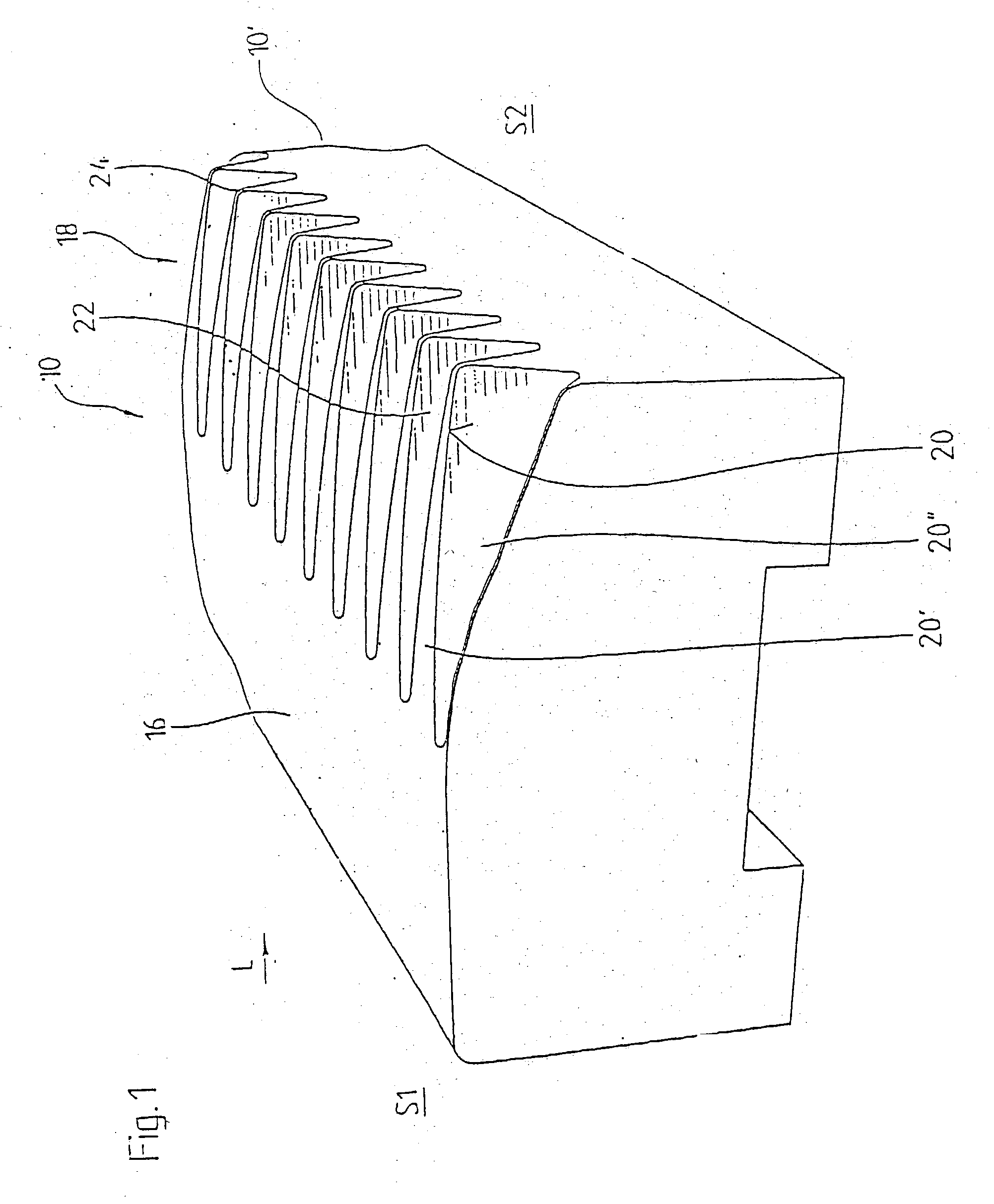
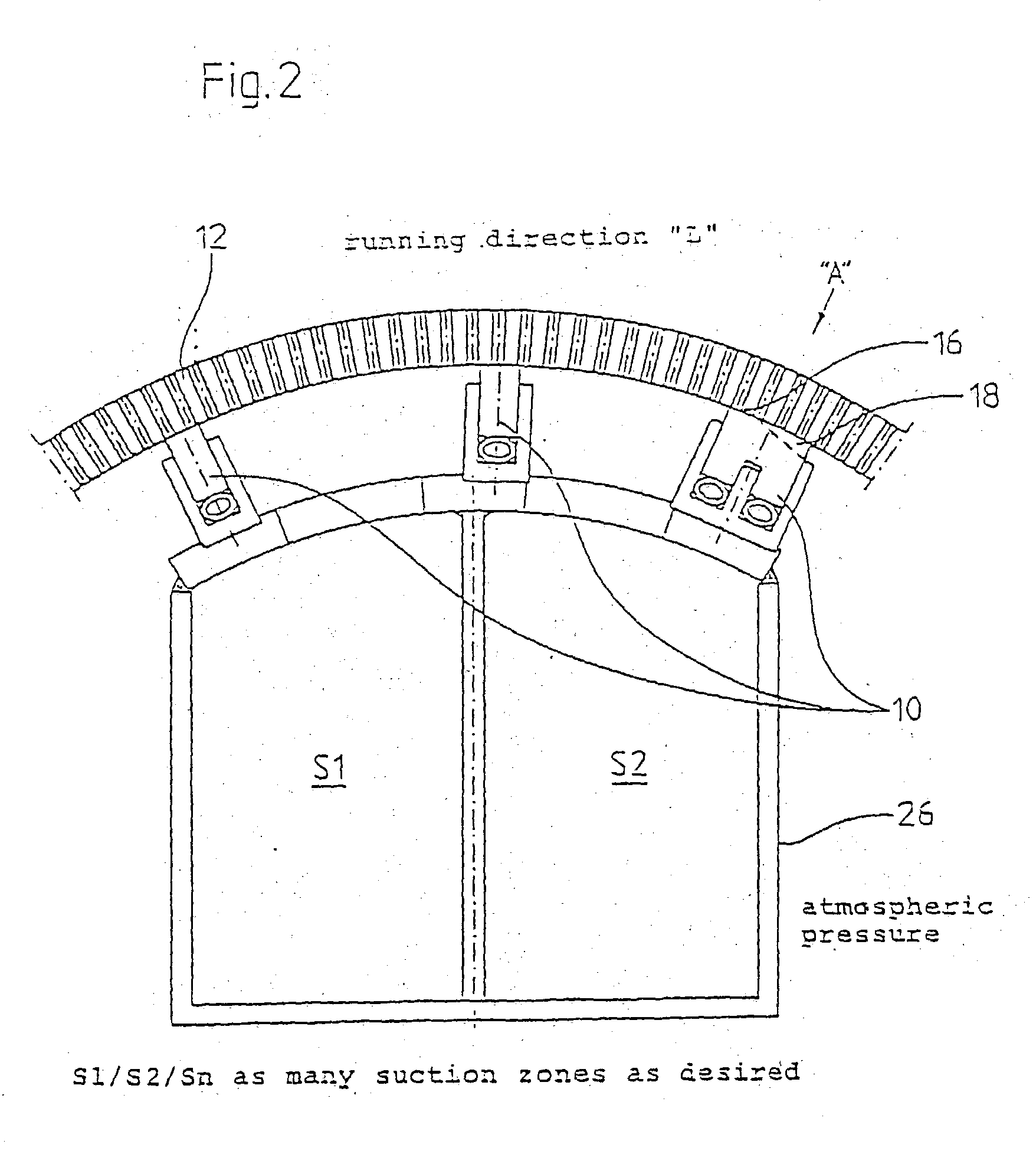
[0082] FIG. 1 shows, in a schematic perspective part illustration, a purely exemplary embodiment of a sealing element 10 of a sealing device which is arranged, for example, inside a suction roll of a paper making machine and which can cooperate with the inner wall of the roll jacket 12 (see also FIGS. 2 and 3). As many s...


PUM


Abstract

Sealing device for sealing at least one zone of underpressure or overpressure adjoining a moving surface that includes at least one sealing element, positionable opposite the moving surface to form a front and a rear, with respect to a surface running direction. The sealing device includes a sealing section located at the front and a ventilation section located at the rear. The sealing section is structured to sealingly interact with the moving surface; and the ventilation section is structured and arranged to form a gap with the moving surface that widens in the surface running direction.

Description

[0001] The present application is a continuation of U.S. patent application Ser. No. 10 / 090,172 filed Mar. 5, 2002 that claims priority under 35 U.S.C. .sctn. 119 of German Patent Application No. 101 10 946.6 filed Mar. 7, 2001, the disclosures of which are expressly incorporated by reference herein in their entireties.[0002] 1. Field of the Invention[0003] The invention relates to a sealing device for the sealing of at least one zone of underpressure or overpressure adjoining a moved surface in a paper making machine. The sealing device includes at least one sealing element disposed opposite the moved surface. Such a sealing device is known, e.g., from DE-A-197 51 283 (see FIG. 15).[0004] 2. Discussion of Background Information[0005] Such sealing devices are used in practice both in the former part and in the press part and / or the dryer part of a respective paper machine, where they can be used in, among other things, suction rolls or blow rolls. For instance, as a rule, suction ro...

Claims


Application Information

Patent Timeline
Patent Type & Authority Applications(United States)
IPC IPC(8): D21F3/10
CPCD21F3/10
Inventor SCHREFL, HERBERTKEINBERGER, RUDIGERWEISS, VALENTINLUGER, ANTON
Owner VOITH PATENT GMBH
Why Eureka
Try Eureka