Slitting mechanism for glass wool

A glass wool and cutting needle technology, which is used in metal processing, smoke removal, cleaning methods and utensils, etc., can solve the problems of not having a fast and clean cutting method, uneven layers of glass wool cross-sections, etc. The effect of clean cross section and preventing excessive friction

Pending Publication Date: 2022-03-18
九江润诚新材料有限公司
View PDF0 Cites 0 Cited by
  • Summary
  • Abstract
  • Description
  • Claims
  • Application Information

AI Technical Summary

Problems solved by technology

[0005] The purpose of the present invention is to provide a glass wool cutting mechanism to solve the existing glass wool cutting mechanism proposed in the above-mentioned background technology, through the cutting of the fluffy gla

Method used


Image

  • Slitting mechanism for glass wool
  • Slitting mechanism for glass wool
  • Slitting mechanism for glass wool

Examples


Embodiment 1

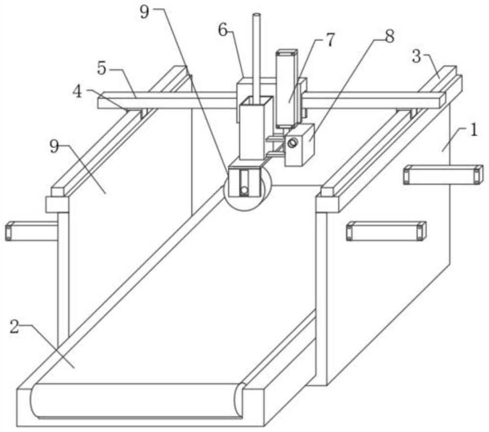
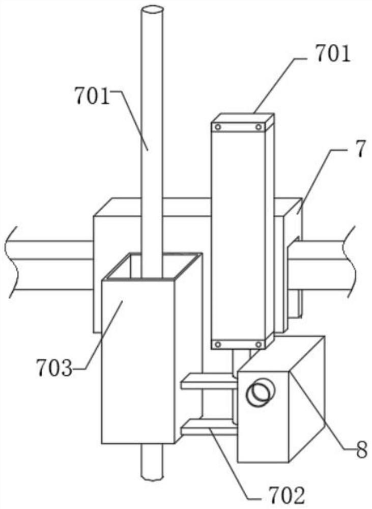
[0029] See 1- Figure 7 , in an embodiment of the present invention, a glass wool slitting mechanism includes: a working chamber 1, a conveyor belt 2 is installed at the lower end of the inner cavity of the working chamber 1, a guide rail 3 is fixed on the upper end of the working chamber 1, and a sliding sleeve on the surface of the guide rail 1 A sliding sleeve 4 is connected, and the upper surface of the sliding sleeve 4 is fixed with a sliding rail 2 5, and the surface of the sliding rail 2 5 is slidably connected with a sliding sleeve 2 6; the cutting assembly 7 arranged on the surface of the sliding sleeve 6, the cutting assembly 7 includes A hydraulic rod 701 fixed on the surface of the sliding sleeve 26, a mounting plate 702 is fixed on the telescopic end of the hydraulic rod 701, a sleeve 703 is fixed on one side of the mounting plate 702, and a screw rod 704 is threaded on both sides of the sleeve 703, and the screw rod 704 is close to One end of the centerline of th...

Embodiment 2

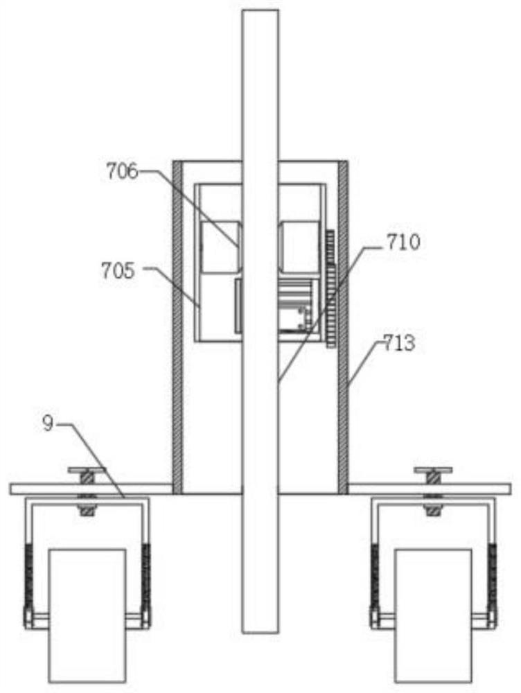
[0031] see Image 6 The difference from Embodiment 1 is that the exhaust assembly 8 includes: a box body 801 fixed on the other side of the mounting plate 702, and the two sides of the box body 801 are fitted with an air intake pipe 802, and the air intake pipe 802 is close to the center line of the box body 801 An air pump 803 is fixed at one end, a cloth bag 804 is fixed at the middle end of the inner cavity of the box body 801, an activated carbon net 805 is fixed at the lower end of the inner cavity of the box body 801, a conical cylinder 806 is fixed at the lower end of the box body 801, and the output end of the conical cylinder 806 is connected to the conveyor belt 2. The upper part is set opposite to each other. At the same time, the air pump 803 is working. The smoke generated during cutting can be sucked into the box 801 through the intake pipe 802, and the gas is filtered through the cloth bag 804 and the activated carbon net 805 in the box 801, and then passed throu...

Embodiment 3

[0033] see Figure 7The difference from Embodiment 1 is that the pressing assembly 9 includes: a horizontal plate 901 fixed on both sides of the lower end of the sleeve 703, a sleeve plate 902 is provided under the horizontal plate 901, and a waist groove 903 is opened on both sides of the sleeve plate 902, The inner cavity of the waist groove 903 is slidingly sleeved with an I-shaped block 904, a spring 905 is fixed between the I-shaped block 904 and the inner cavity of the waist groove 903, and a cross bar 906 is fixed horizontally between the two I-shaped blocks 904, and the surface of the cross bar 906 A pressure roller 907 is sleeved, and a casing 908 is embedded in the inner cavity of the three sleeve plates 902. A bolt 909 is connected between the sleeve plate 902 and the horizontal plate 901. Through the bolt 909, the sleeve plate 902 and the horizontal plate 901 can be installed or disassembled. , when cutting, the surface of the glass wool can be squeezed by the pres...


PUM


Abstract

The glass wool slitting mechanism comprises a working bin, a conveying belt is installed at the lower end of an inner cavity of the working bin, a first guide rail is fixed to the upper end of the working bin, the surface of the first guide rail is slidably sleeved with a first sliding sleeve, and a second sliding rail is fixed to the upper end face of the first sliding sleeve. According to the glass wool cutting device, when the glass wool cutting device is used for cutting, the cutting area of glass wool can be extruded through the two pressing rollers, so that the fluffy glass wool cutting area is compressed, the thickness of the glass wool cutting area is reduced, compared with an existing direct cutting mode, the cross section cut by the glass wool cutting device is neater, the situation of uneven layers is prevented, and the cutting efficiency is improved. And when the glass wool is extruded by the pressing roller, the pressing roller can rise and fall in the sleeve plate through the spring and roll at the same time, the situation that the glass wool cutting area is broken due to excessive extrusion force is prevented, excessive friction force is prevented from being generated between the pressing roller and the glass wool during cutting, and the cotton pressing assembly can be conveniently and rapidly disassembled and assembled by rotating the bolt.

Description

technical field [0001] The invention relates to the field of glass wool cutting equipment, in particular to a glass wool cutting mechanism. Background technique [0002] Glass wool belongs to a category of glass fiber. It is a kind of man-made inorganic fiber. Glass wool is a material made of molten glass fiberized to form cotton. Its chemical composition belongs to glass. It is an inorganic fiber with good shape and volume. Small density, low thermal conductivity, thermal insulation, good sound-absorbing performance, corrosion resistance, and stable chemical properties. It is often used as sound-absorbing cotton, and is also widely used in thermal insulation of equipment. [0003] The existing glass wool slitting mechanism, in the process of its use, cuts the fluffy glass wool by the cutting knife, and the situation of uneven glass wool cross-section is prone to occur, so that the cutting of glass wool needs secondary treatment , does not have a quick and clean cutting met...

Claims


Application Information

Patent Timeline
IPC IPC(8): B26F3/08B26D7/08B26D7/06B26D7/32B08B15/04
CPCB26F3/08B26D7/08B26D7/0625B26D7/32B08B15/04
Inventor 潘友根周倬周智
Owner 九江润诚新材料有限公司
Why Eureka
Try Eureka