Workpiece transport apparatus

a technology for transporting apparatuses and workpieces, applied in forging presses, charge manipulation, furnaces, etc., can solve the problems of reducing the reliability of chucks, increasing the likelihood of workpiece droppage, cracking, chipping and/or other such problems, and making chucking all the more difficult, so as to prevent the occurrence of workpiece droppage, reduce the generation of particles, and eliminate mechanical parts.

Inactive Publication Date: 2004-10-07
SHARP KK
View PDF8 Cites 66 Cited by
  • Summary
  • Abstract
  • Description
  • Claims
  • Application Information

AI Technical Summary

Benefits of technology

0019] As a result of such specific features, workpiece(s) lifted in floating fashion at one transport stage or set of transport stages by fluidic expulsion and / or simultaneous expulsion and suction is / are rotated by rotating mechanism(s) and pair(s) of transport stages is / are inverted vertically while workpiece(s) is / are held by fluidic suction to the one transport stage or set of transport stages; following which reduction, termination, and / or reversal of fluidic suction from one transport stage or set of transport stages now occupying upper location(s) causes, in accompaniment to such reduction, termination, and / or reversal of suction, workpiece(s) to be transferred from one transport stage or set of transport stages at upper location(s) to other transport stage or set of transport stages at lower location(s) such that workpiece(s) is / are lifted in floating fashion by fluidic expulsion and / or simultaneous expulsion and suction at the other transport stage or set of transport stages. As a result, even where increased size of workpiece(s) causes occurrence of bowing at workpiece(s) and / or where workpiece(s) was / were already bowed at the outset, workpiece(s) lifted in floating fashion at one transport stage or set of transport stages by fluidic expulsion and / or simultaneous expulsion and suction is / are smoothly flipped so as to reverse front and back sides thereof while workpiece(s) is / are held by fluidic suction to the one transport stage or set of transport stages; following which reduction, termination, and / or reversal of fluidic suction at one transport stage or set of transport stages now occupying upper location(s) is accompanied by transfer of workpiece(s) from one transport stage or set of transport stages to other transport stage or set of transport stages at lower location(s) such that workpiece(s) is / are lifted in floating fashion thereabove, making it possible to definitively prevent occurrence of workpiece droppage, breakage, cracking, chipping and / or the like during transport and / or flipping to reverse front and back sides thereof.
0020] Furthermore, it being possible to carry out chucking of workpiece(s) by mere fluidic suction, and chucking of workpiece(s) by mechanical part(s) being unnecessary, it is possible to reduce generation of particles to the maximum extent and it is possible to eliminate mechanical parts, simplify servicing procedures, and make the apparatus more compact.
0021] Moreover, if at least a portion of the respective transport stages is or are supported so as to permit horizontal and vertical movement, it will be possible to definitively prevent interference between transport stage(s) and nearby component(s) as transport stage(s) is / are rotated during flipping of workpiece(s) to reverse front and back sides thereof, making it possible to smoothly carry out flipping of workpiece(s) to reverse front and back sides thereof.

Problems solved by technology

However, with the foregoing conventional workpiece transport apparatus, because workpiece 201 is chucked by chuck appendages 203 of plurality of mechanical chuck means 202, . . . , increase in the size of the workpiece will cause occurrence of bowing at the workpiece, reducing chuck reliability.
This increases the likelihood of occurrence of workpiece droppage, breakage, cracking, chipping and / or other such problems during transport and flipping to reverse front and back sides thereof.
And where the workpiece was already bowed at the outset, chucking is made all the more difficult.
And because there are many mechanical parts and apparatus constitution is complex, not only is failure likely to occur and much labor expended during servicing thereof, but the apparatus also tends to be large in size.
In addition, where a vacuum chuck or electrostatic chuck is employed instead of a mechanical chuck, a possibility exists that generation of static electricity will affect the workpiece and / or the process.

Method used


Image

  • Workpiece transport apparatus
  • Workpiece transport apparatus
  • Workpiece transport apparatus

Examples


first embodiment

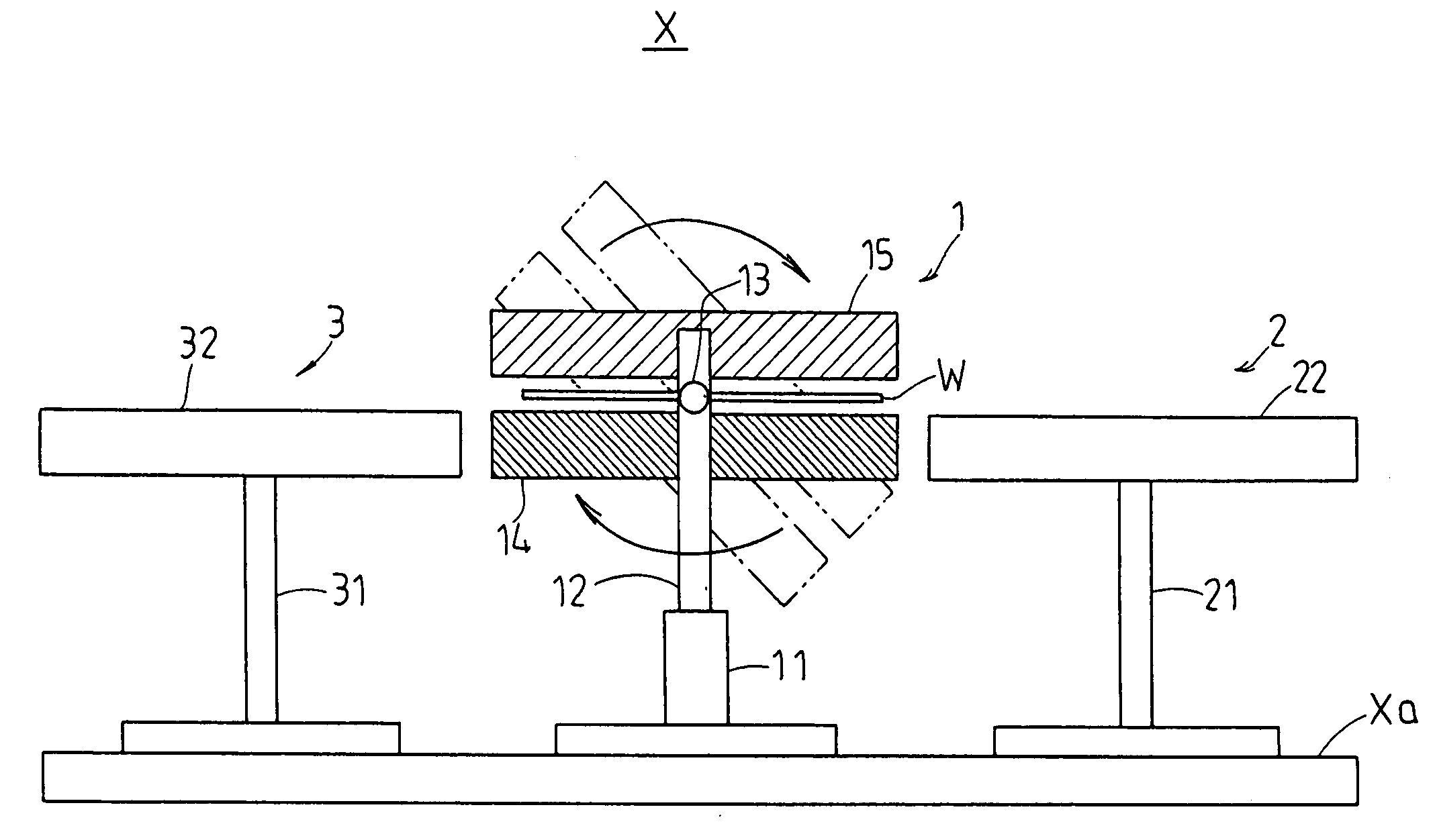
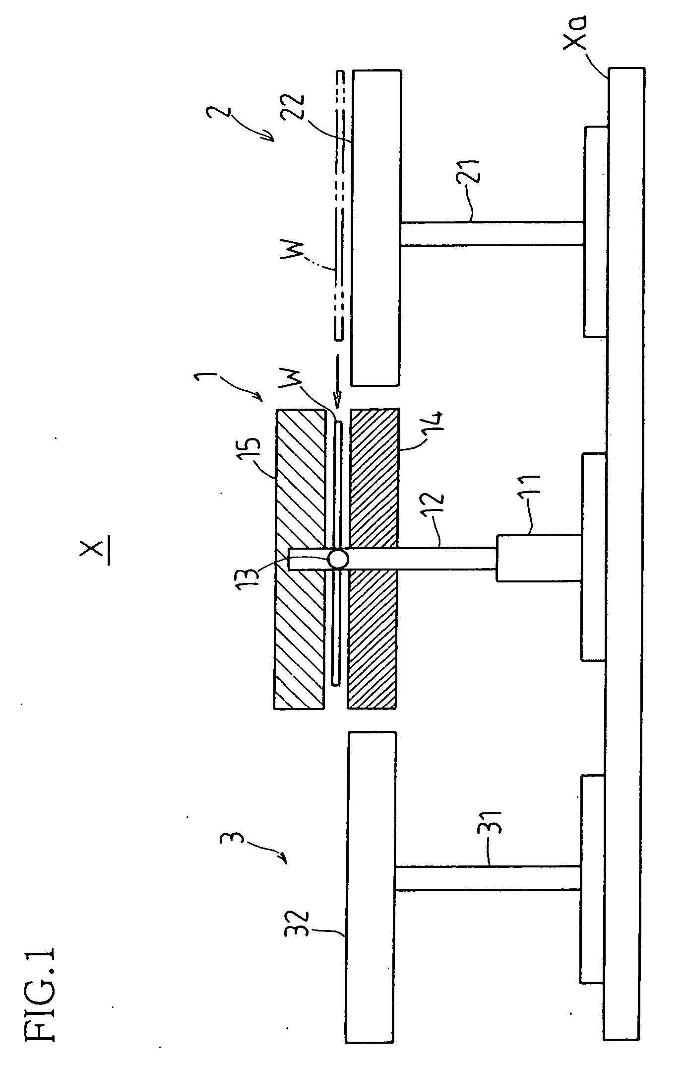
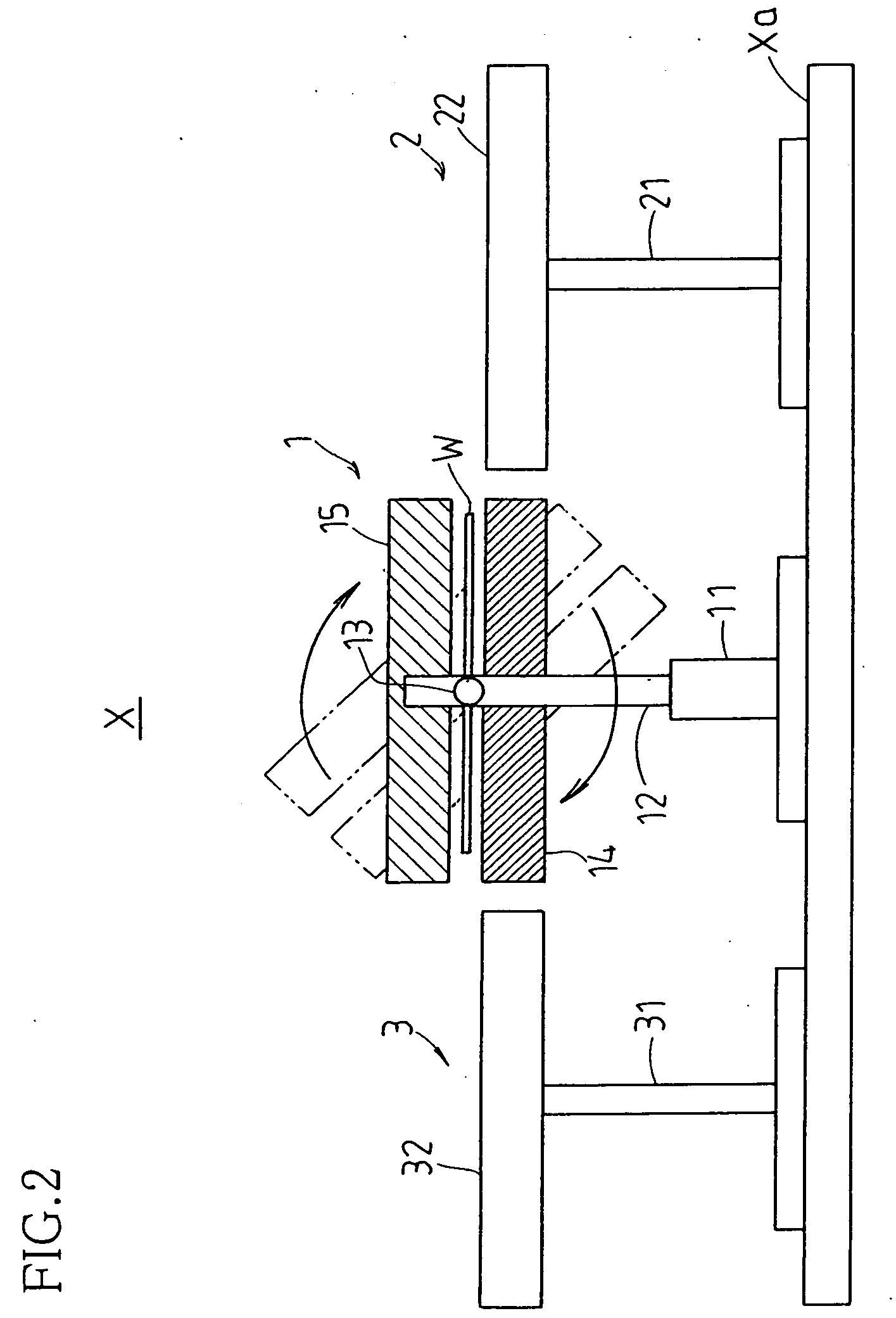
[0044] FIGS. 1 through 3 show workpiece transport apparatus X associated with a first embodiment of the present invention. Arranged so as to be lined up in a single row over platform Xa are workpiece rotation region 1, which flips workpiece W so as to reverse front and back sides thereof; workpiece introduction region 2, which transports workpiece W to workpiece rotation region 1; and workpiece exit region 3, to which workpiece W is transported from workpiece rotation region 1. In the present case, glass substrate(s), semiconductor wafer(s), and / or other such more or less rectangular object(s) in connection with manufacture of semiconductor, liquid crystal display element, EL, PDP and / or other such flat panel display, solar cell panel, and / or the like may be employed as workpiece(s) W.

[0045] The foregoing workpiece rotation region 1 is equipped with pair of left and right support legs 11 (only that at the foreground in the plane of the paper being shown in FIGS. 1 through 3) install...

second embodiment

[0058] Next, referring to FIGS. 10 through 13, a second embodiment of the present invention is described.

[0059] In the present embodiment, constitutions of first and second transport stages are modified Note that, except for the first and second transport stages, the constitution is in other respects identical to that of the foregoing first embodiment, and like components will be assigned like reference numerals and detailed description thereof will be omitted.

[0060] That is, in the present embodiment, as shown in FIGS. 10 through 13, gas expulsion orifices 41c, 42c which expel gas by way of plurality of supply passages 41b, 42b and gas suction orifices 41d, 42d which suck gas by way of plurality of suction passages 41e, 42e are disposed in alternating fashion so as not to mutually crowd each other in region(s) near the centers of facing surfaces 41a, 42a of first and second transport stages 41, 42 of workpiece rotation region 4. Moreover, the constitution is such that there is / are ...

third embodiment

[0070] Next, referring to FIGS. 14 through 19, a third embodiment of the present invention is described.

[0071] In the present embodiment, constitution(s) of workpiece rotation region(s) is / are modified. Note that, except for the workpiece rotation region(s), the constitution is in other respects identical to that of the foregoing first embodiment, and like components will be assigned like reference numerals and detailed description thereof will be omitted.

[0072] That is, as shown in FIGS. 14 and 15, disposed between workpiece introduction region 2 and workpiece exit region 3 in the present embodiment there are upstream workpiece rotation region 5 which is upstream in the workpiece transport direction, and downstream workpiece rotation region 6 which is downstream in the workpiece transport direction; this upstream workpiece rotation region 5 and this downstream workpiece rotation region 6, as well as this workpiece introduction region 2 and this workpiece exit region 3, being arrang...


PUM


Abstract

While periphery or peripheries of workpiece(s) W lifted in floating fashion by simultaneous suction and expulsion of gas(es) between pair(s) of first and second, or upper and lower, transport stages 14, 15 is/are retained by plurality of elevator pins 16, respective transport stage(s) is/are inverted vertically and workpiece(s) is/are transferred from upper first transport stage(s) to lower second transport stage(s) such that workpiece(s) W is/are lifted in floating fashion thereabove by simultaneous suction and expulsion of gas(es) in accompaniment to lowering of respective elevator pin(s) at said first transport stage(s).

Description

[0001] This application claims priority under 35 USC 119(a) to patent application No. 2003-75948 filed in Japan on 21 January 2003, the content of which is incorporated herein by reference in its entirety.BACKGROUND OF INVENTION[0002] The present invention pertains to a workpiece transport apparatus transporting glass substrate, semiconductor wafer, and / or other such workpiece during manufacture of semiconductor, liquid crystal display element, EL (electroluminescent), PDP (plasma display panel) and / or other such flat panel display, solar cell panel, and / or the like; and is in particular related to a strategy for smoothly flipping a workpiece so as to reverse front and back sides thereof for the purpose of carrying out processing of the backside, and / or of both sides, of the workpiece.[0003] During cleaning, photolithography, and / or other such operations carried out on glass substrates and / or semiconductor wafers (hereinafter collectively referred to as "workpiece(s)") at sites at w...

Claims


Application Information

Patent Timeline
Patent Type & Authority Applications(United States)
IPC IPC(8): B65G47/248B65G47/252B65G49/06H01L21/677H01L21/683
CPCB65G47/252B65G49/061B65G49/065B65G49/067B65G2249/04B65G2249/045H01L21/67784H01L21/6838
Inventor SUGIYAMA, AKIRANAKAMURA, TSUNEOYAMAMOTO, TATSUSHI
Owner SHARP KK
Why Eureka
Try Eureka