Blade mounting device

a blade-mounting device and mounting plate technology, applied in poultry eviscerating devices, fish processing, poultry processing, etc., can solve the problems of excessive force exerted by the retaining strip on the blade, the blade-mounting device needs to be removed from the machine, and the thread wear

Inactive Publication Date: 2004-10-07
MAJA-MASCHINENFABRIK HERMAN SCHILL KG
View PDF5 Cites 7 Cited by
  • Summary
  • Abstract
  • Description
  • Claims
  • Application Information

AI Technical Summary

Problems solved by technology

These have the disadvantage that in order to remove the blade or for cleaning of the gaps between blade, blade support and retaining strip, the entire blade-mounting device needs to be removed from the machine, since the screws are otherwise not accessible.
In addition, the repeated opening and closing of the bolt connection leads to wear of the threads.
It proves to be unfavorable with this device that the force exercised by the retaining strip on the blade is punctually larger in the area of the screws than in the remaining areas.
In addition the disadvantage exists that for removing or cleaning the blade and the gaps between blade, blade support and retaining strip the entire retaining strip must be removed from the blade-mounting device and be put down in another place.
If the retaining strip is not put on accurate, then the edges of the recess can be damaged.
This can lead to the fact that no sufficient forces can be applied when clamping the retaining strip and the blade support for clamping the blade.
It is thereby not possible to jam or damage the shoulders when putting the retaining strip on the blade support and when tightening it.

Method used


Image

  • Blade mounting device
  • Blade mounting device
  • Blade mounting device

Examples


Embodiment Construction

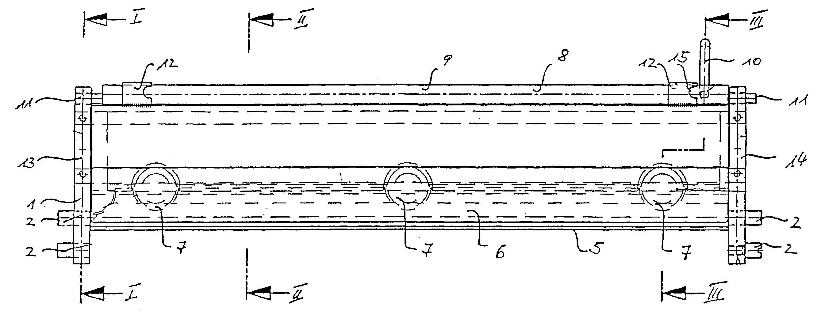
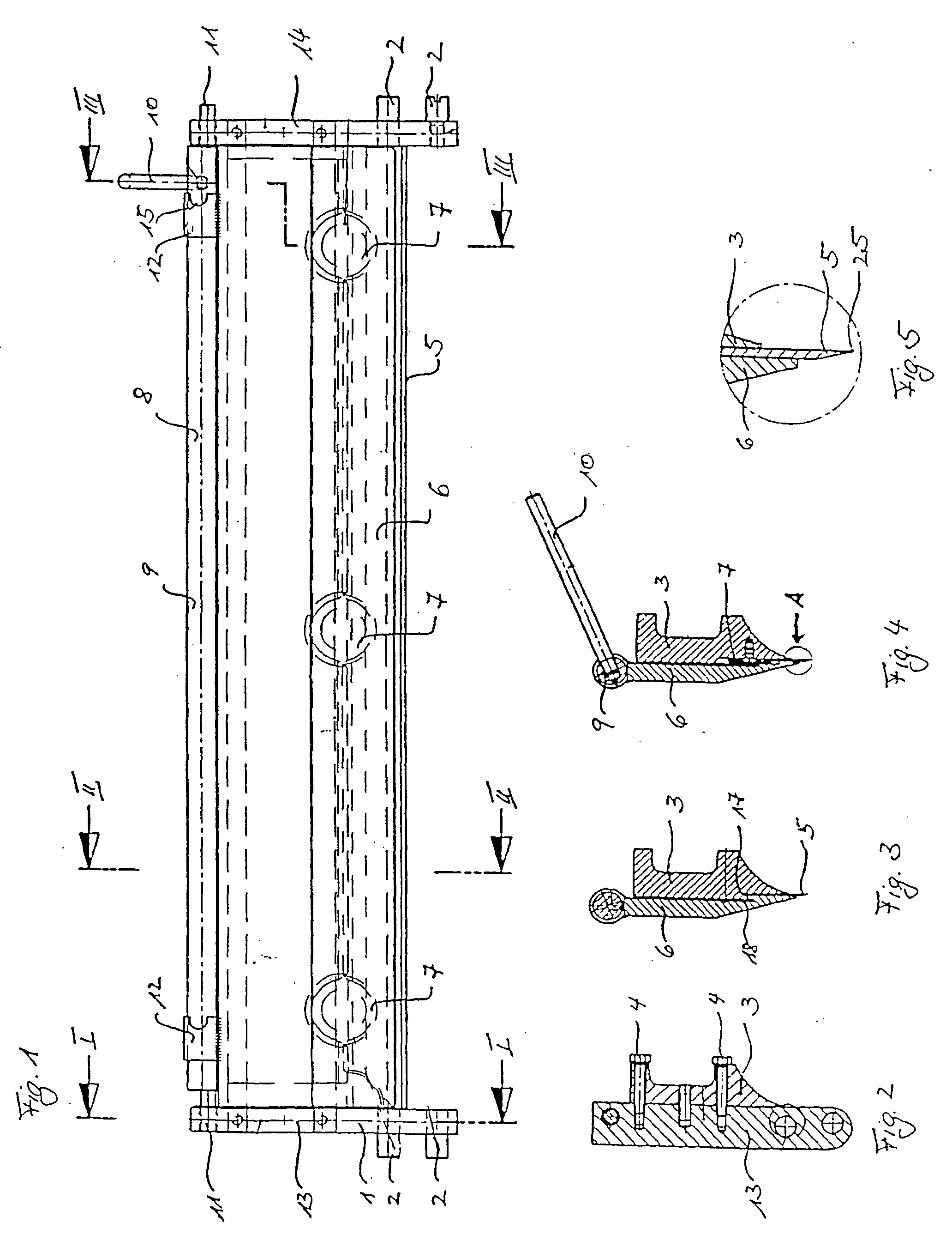
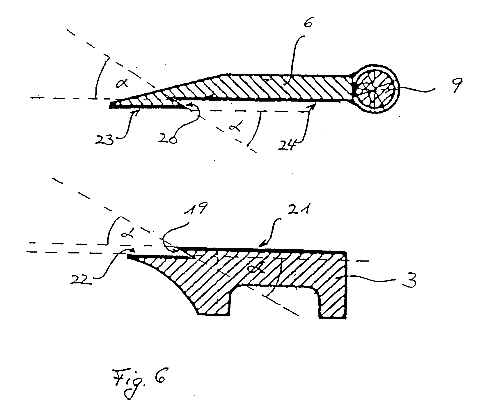
[0019] In FIGS. 1 to 4 a blade-mounting device is represented in a view from above and in various cutting planes. A blade mount suspension 1 exhibits lateral pegs 2, with which the blade-mounting device can be hung up into a skinning and slab removal machine. A blade support 3 is fastened with screws 4 to the blade mount suspension 1, as can be seen in FIG. 2. The blade support cannot be seen in FIG. 1, since it is located at the bottom part of the blade-mounting device. A blade 5 is laid on the blade support, which is clamped on the blade support by means of a retaining strip 6. Disks 7 are intended as stop for the blade, on which the blade with the side facing away from the cutting edge is laid against. The disks are attached by means of a screw to the surface of the blade support that is facing the retaining strip. The disks 7 are shown only dashed in FIG. 1, since they are not observable by the viewer in this view. They can however be seen in the sectional view in accordance wit...


PUM


Abstract

A blade mounting device for the mounting of blades, in particular, for skinning and stripping machines with a blade mount fixing (1), a blade support (3), a retaining strip (6) and a tensioning device (8) for holding the blade support and retaining strip together is disclosed. A swallow-tail shaped recess (17, 18) is provided across the total width of the facing surfaces of the blade support and retaining strip. A shaft (9), centrally mounted in the retaining strip (6) and eccentrically mounted in the blade mount fixing (1) serves as tensioning device.

Description

STATE OF THE ART[0001] The invention originates from a blade-mounting device according to the generic term of claim 1.[0002] Such blade-mounting devices are used in particular for skinning and slab removal machines during meat, fish and poultry processing. For the removal of skin or slab the processing goods are pressed against a blade and moved in relation to the blade. The blade is clamped between a blade support on the one hand and a retaining strip on the other hand. The blade support is fastened to a blade mount suspension, which is used in the machine, in particular a skinning and slab removal machine.[0003] In order to hold the blade between the blade support and the retaining strip and to prevent shifting of the same, the blade support and retaining strip are pressed together. For this purpose bolt connections are well-known from the state of the art. These have the disadvantage that in order to remove the blade or for cleaning of the gaps between blade, blade support and re...

Claims


Application Information

Patent Timeline
Patent Type & Authority Applications(United States)
IPC IPC(8): A22C17/12B26D7/26
CPCA22C17/12B26D7/2614
Inventor SCHILL, JOACHIM
Owner MAJA-MASCHINENFABRIK HERMAN SCHILL KG
Why Eureka
Try Eureka