Drive control of power system including fuel cells

a technology of power system and fuel cell, which is applied in the direction of battery/fuel cell control arrangement, electrochemical generators, transportation and packaging, etc., can solve the problems of increasing the size of the whole system, frequent temporary stoppage of the fuel gas generation system, and significant energy loss, so as to improve the convenience of the power system, improve the power generation efficiency of the fuel cell, and improve the power generation efficiency

Inactive Publication Date: 2004-10-28
TOYOTA JIDOSHA KK
View PDF8 Cites 19 Cited by
  • Summary
  • Abstract
  • Description
  • Claims
  • Application Information

AI Technical Summary

Benefits of technology

[0011] In the power system of the invention, hydrogen remains in the hydrogen separation module when the fuel gas generation system temporarily stops supply of the fuel gas and execute the stop control in the hydrogen no-purge mode. This arrangement ensures a quick supply of hydrogen to the fuel cells in response to an output demand, thus desirably shortening a restart time of the fuel gas generation system and reducing a potential energy loss.
[0055] The fuel gas generation system is driven under relatively high temperature conditions. The `lower limit` represents a threshold value that allows the fuel gas generation system to generate hydrogen. When the observed temperature at the specified position is not higher than the lower limit, supply of the material does not result in generation of hydrogen. In this case, the mobile object of this application does not execute the restart control discussed above in response to a restart request but warms up the fuel gas generation system. This arrangement ensures the adequate operations of the power system.

Problems solved by technology

On the vehicle, however, the fuel gas generation system is subjected to frequent temporary stops, for example, during a stop at a traffic light and during a drive on a downslope.
Removal of hydrogen from the hydrogen separator unit at every temporary stop undesirably lengthens a restart time of the system and causes a significant energy loss.
The presence of the hydrogen reservoir, however, undesirably increases the size of the whole system and complicates the system configuration.
During the stop control in the hydrogen no-purge mode, a decrease in temperature of the hydrogen separation membrane to or below a preset level may cause hydrogen brittleness of the hydrogen separation membrane.
The temperature drop may also lead to hydrogen-induced deterioration of the other constituents of the fuel gas generation system.
The long-time operation of the temperature retention module leads to an energy loss of the power system.
The stop control in the hydrogen purge mode replaces hydrogen in the hydrogen separation module with the purge gas and can thus not quickly supply hydrogen at the time of a restart.
When the output demand is greater than the preset level, the greater supply of the material than the normal supply in the state of normal operations may cause an excess supply and lower the efficiency of the power system.
The fuel cells may have poor power generation efficiency, when the output demand is not greater than the preset level.
Under the conditions of poor power generation efficiency of the fuel cells, the power system of this application stops output of electric power from the fuel cells, executes the stop control in the hydrogen no-purge mode, and controls the secondary battery to output electric power.
When the starter switch of the motor is set off; there is a high possibility that the fuel gas generation system stops for a long time period.
As discussed above, when the output demand to the fuel cells is not greater than the preset level, the fuel cells may have poor power generation efficiency.
The moving speed of not higher than the preset level may thus cause the poor power generation efficiency of the fuel cells.
The vehicle speed of not higher than SPD_ref may worsen the power generation efficiency of the fuel cells 18.
The accelerator opening of not greater than ACC_ref suggests a low output demand, which leads to deterioration of the power generation efficiency of the fuel cells 18.
Such replacement interferes with a quick supply of hydrogen at the time of a restart.

Method used


Image

  • Drive control of power system including fuel cells
  • Drive control of power system including fuel cells
  • Drive control of power system including fuel cells

Examples


Embodiment Construction

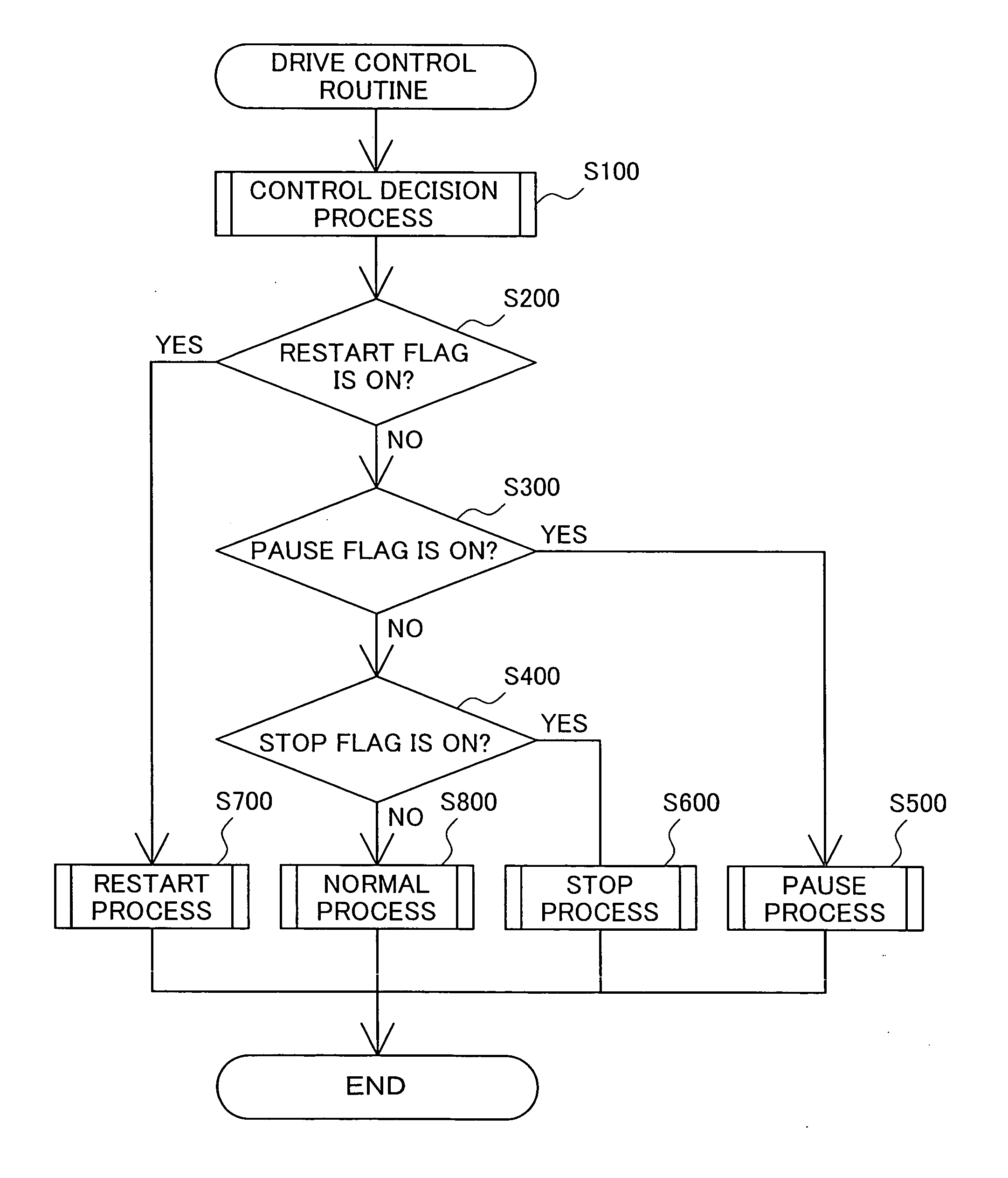
[0145] In the above embodiment, the control decision process shown in the flowchart of FIG. 5 sets the respective flags according to the various conditions. These conditions and their combination may be set arbitrarily.

[0146] D2. Modified Example 2

[0147] The procedure of the above embodiment selects either the pause process or the stop process at the start of the stop control of the fuel gas generation system. One possible modification may omit such selection but may unconditionally execute the pause process and then change over the stop control to the stop process based on the various parameters.

[0148] D3. Modified Example 3

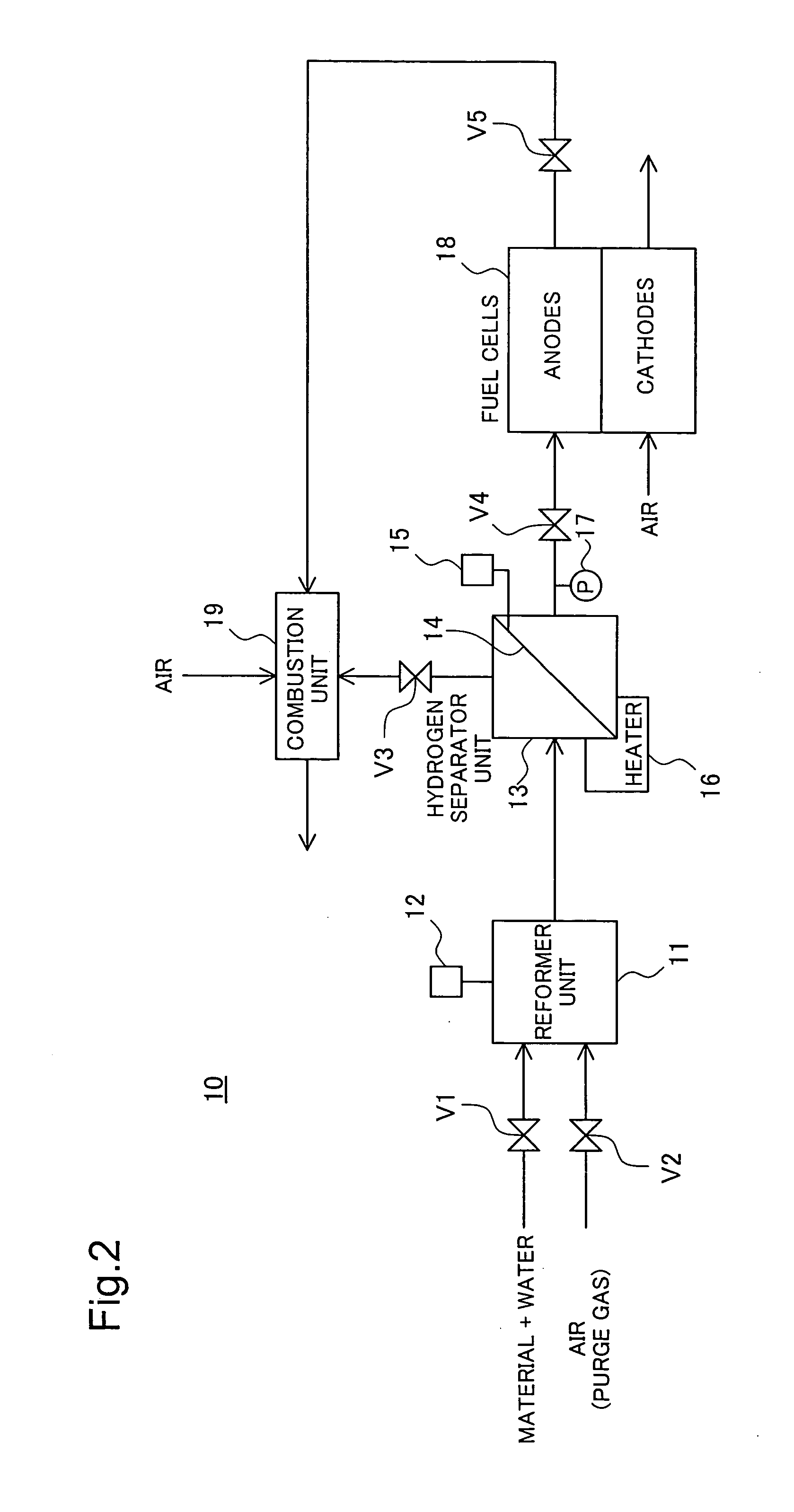
[0149] The pause process of the second embodiment changes over the positions of the valves with elapse of the time period Tr at step S520a in the flowchart of FIG. 10. This is, however, not restrictive. For example, the hydrogen separator unit 13 may have a sensor for measuring the concentration of hydrogen, and the stop process may change over the positions of ...


PUM

PropertyMeasurementUnit
temperatureaaaaaaaaaa
pressureaaaaaaaaaa
timeaaaaaaaaaa

Abstract

A power system of the invention includes fuel cells and a fuel gas generation system that generates a fuel gas to be supplied to the fuel cells. At the time of stopping supply of hydrogen, the fuel gas generation system selectively uses a stop process that replaces hydrogen in a hydrogen separator unit with the air for removal of hydrogen and a pause process that allows hydrogen to remain in the hydrogen separator unit. The stop process is selected when the fuel gas generation system stops the supply of hydrogen for a long time period. The pause process is selected when the fuel gas generation system temporarily stops the supply of hydrogen. The arrangement of the invention desirably shortens a restart time of the fuel gas generation system and reduces a potential energy loss.

Description

[0001] 1. Field of the Invention[0002] The present invention relates to a drive control technique of a power system including fuel cells.[0003] 2. Description of the Related Art[0004] Various power systems have been developed and proposed, which include fuel cells and a fuel gas generation system for generating a fuel gas to be supplied to the fuel cells and output electric power. In some type of the known fuel gas generation systems, a reformer reforms a material like gasoline or methanol to produce a hydrogen-containing gaseous mixture and a hydrogen separator unit with a hydrogen separation membrane extracts hydrogen from the gaseous mixture.[0005] In this known fuel gas generation system with the hydrogen separation membrane, some techniques of removing hydrogen from the hydrogen separator unit at a stop of the system have been proposed to prevent hydrogen brittleness of the hydrogen separation membrane (for example, see Patent Laid-Open Gazette No. 2001-118594 and No. 2002-9344...

Claims


Application Information

Patent Timeline
Patent Type & Authority Applications(United States)
IPC IPC(8): H01M8/00B60L11/18C01B3/02H01M8/04H01M8/06H01M8/10H01M16/00
CPCB60L11/1885H01M8/04231H01M8/0432H01M8/04373H01M8/04753H01M8/04947H01M8/0612H01M16/006Y02E60/50Y02T90/34B60L58/31Y02E60/10Y02T90/40
Inventor AOYAMA, SATOSHIOGINO, SHIGERUIZAWA, YASUHIROIGUCHI, SATOSHIMASUI, TAKATOSHI
Owner TOYOTA JIDOSHA KK
Why Eureka
Try Eureka