Conduction and correction of a light beam

a light beam and light beam technology, applied in the field of curved optical refraction equipment, can solve the problems of undesirable damping, significant astigmatism, special astigmatism, etc., and achieve the effect of enhancing the measuring response, less optical signal, and avoiding problems caused by crosstalk from well to well

Inactive Publication Date: 2004-11-04
THERMO ELECTRONICS OY
View PDF13 Cites 3 Cited by
  • Summary
  • Abstract
  • Description
  • Claims
  • Application Information

AI Technical Summary

Benefits of technology

0012] Another benefit of the invention is its ability to function equally well at all wavelengths of light. Thus, one and the same apparatus can be used for processing lights of even highly unequal wavelengths in an equally flawless manner. For example, the wavelength range needed in conventional analyzers can be 200-1000 nm. Efficiency is high as a result of utilizing mirror surfaces over a section as large as possible, and hence a solid angle as large as possible. A large solid angle suppresses respectively less an optical signal, and thus enhances measuring response.
0013] The invention is particularly applicable in optical analyzers, wherein light is conducted to or from a sample. Such analyzers include for example photometers, fluorometers, and luminometers. For example, analyses dealing with clinical chemistry, biochemistry, and molecular biology may involve the use of sample or specimen plates provided with wells having diameters of only 2 mm. Considering tolerances (e.g. positioning), the well in this case has a measuring range whose diameter available for an optical analysis is approximately 1 mm. In addition, the well has an entrance in the form of a narrow tunnel-like passage. According to the invention, this can be managed and, furthermore, the entire solid angle afforded by a well can be deployed. Problems caused by crosstalk from well to well can also be avoided by accurate focusing of light.

Problems solved by technology

Astigmatism is a significant problem also in these cases.
Also in this case astigmatism is a special problem.
If the optics produces a linelike image, only a part of it can thus be used, which causes undesirable damping.
Such a grating is very difficult to prepare.
However, also such a correction works satisfactorily only at certain wave length areas, and the other areas remain rather uncorrected.

Method used


Image

  • Conduction and correction of a light beam
  • Conduction and correction of a light beam
  • Conduction and correction of a light beam

Examples


Embodiment Construction

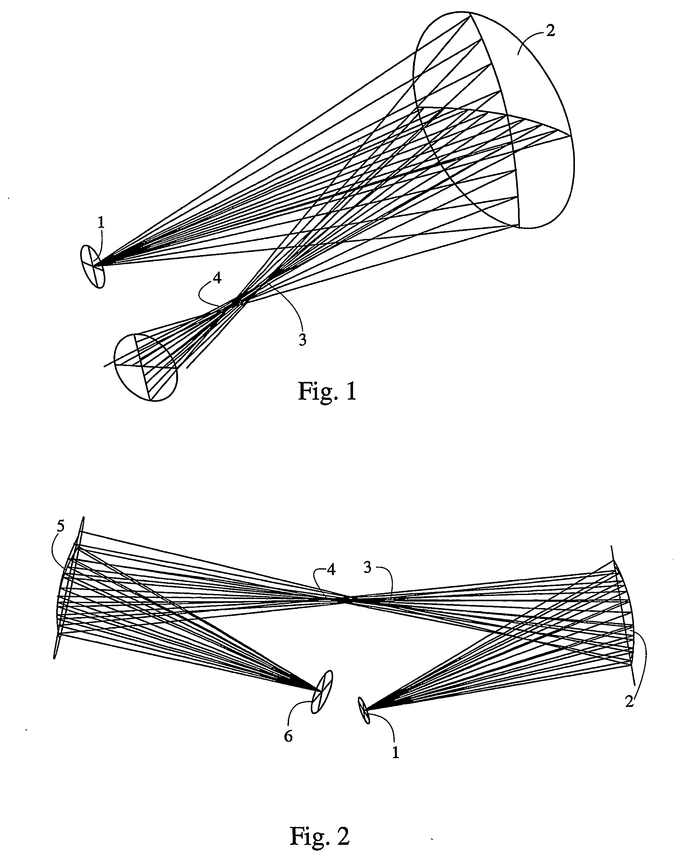
[0043] When an object to be imaged with a spherical mirror lies outside an optical axis, the result will be an astigmatic flaw as a point-like object is visualized as a line segment. The reason for this is that light beams emanating from an object in a variety of planes come to contact with a mirror at different angles, and thus are also reflected at different angles. The extreme cases are created by beams traveling in a plane defined by the point and the main axis (horizontal plane) and in a plane perpendicular thereto (vertical plane). The nearest will be the focus of a beam traveling in the horizontal plane and the farthest will be the focus of a beam traveling in the vertical plane.

[0044] FIG. 1 visualizes the development of astigmatism. An imaging object 1 is focused in the rotational plane (horizontal plane) of a concave spherical mirror 2 at a point 3. In vertical plane, the image shall develop further away at a focus 4, and the focus 3 will be visualized as a vertical line s...


PUM


Abstract

An apparatus for the conduction of light. The apparatus includes two concave refracting elements, such as spherical mirrors or concave gratings, such that a connecting line segment between centers of the elements forms with a main axis of a first element an angle of incidence in excess of zero, and with a main axis of a second element an angle of incidence equal in size but in a plane perpendicular to the plane defined by the connecting line segment and the main axis of the first element. Thus, astigmatism error can be corrected. The apparatus is applicable in optical analyzers for conduction of measuring light to or from a sample.

Description

FIELD OF TECHNOLOGY[0001] The invention relates to curved optical refraction equipment, and deals with conduction of light by means of spherical mirrors or concave gratings. The invention can be applied for example in optical analyzers, such as analyzers in clinical chemistry, which are used for measuring optical radiation emanating from a sample placed in a container.TECHNOLOGICAL BACKGROUND[0002] In optical analyzers, the conduction of measuring light is generally performed by using lens systems. For example, WO 97 / 11354 discloses a fluorometer, wherein a detector is supplied with measuring light from a defined area in a sample well by means of a plane mirror and lenses. The light to be processed in such an apparatus has a wavelength which is typically within the range of 320-800 nm. The effect of imaging errors in lenses, such as dispersion, can be quite extensively minimized in lens optics. Generally, however, correction can only be optimally made on a specific wavelength. When ...

Claims


Application Information

Patent Timeline
Patent Type & Authority Applications(United States)
IPC IPC(8): G01J3/02G01J3/443G02B17/00G01J3/18G02B17/02G02B27/44
CPCG01J3/02G01J3/0208G02B27/4277G02B27/4244G02B17/02
Inventor TUUNANEN, JUKKA
Owner THERMO ELECTRONICS OY
Why Eureka
Try Eureka