
Induction quenching installation, in particular for fabricating suspension components

a technology of induction quenching and fabrication of suspension components, which is applied in the field of induction quenching, can solve the problems of increasing strain, unable to produce high-stressed bars, and the withstandability of such elements is becoming increasingly critical, so as to improve the crystalline structure of metals, improve the bending ability of treated zones, and reduce the effect of strain

Active Publication Date: 2004-11-18
ALLEVARD REJNA AUTOSUSPENSIONS
View PDF3 Cites 21 Cited by
  • Summary
  • Abstract
  • Description
  • Claims
  • Application Information

AI Technical Summary

Benefits of technology

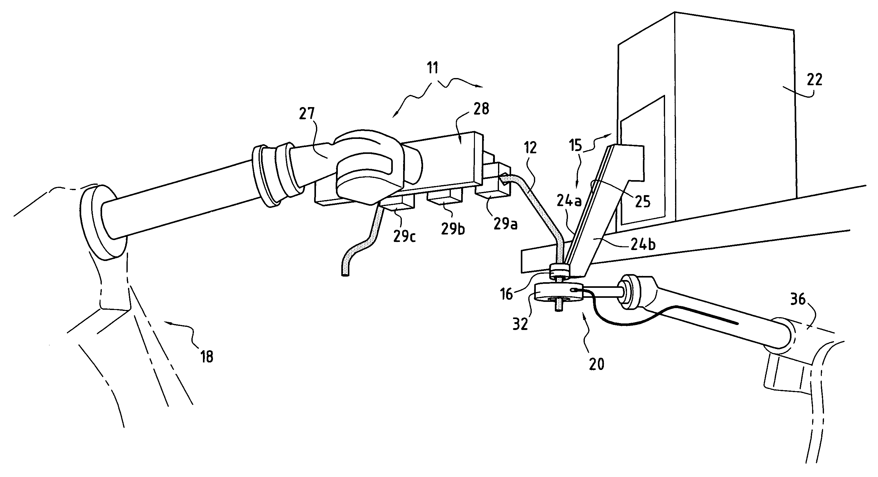
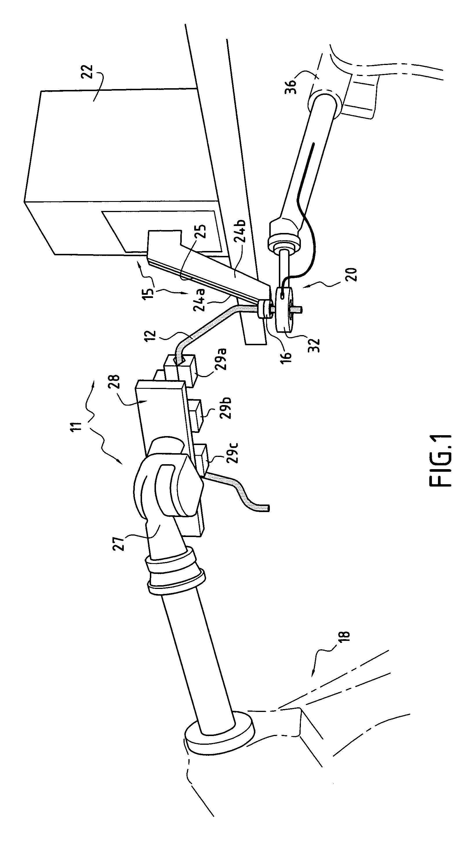
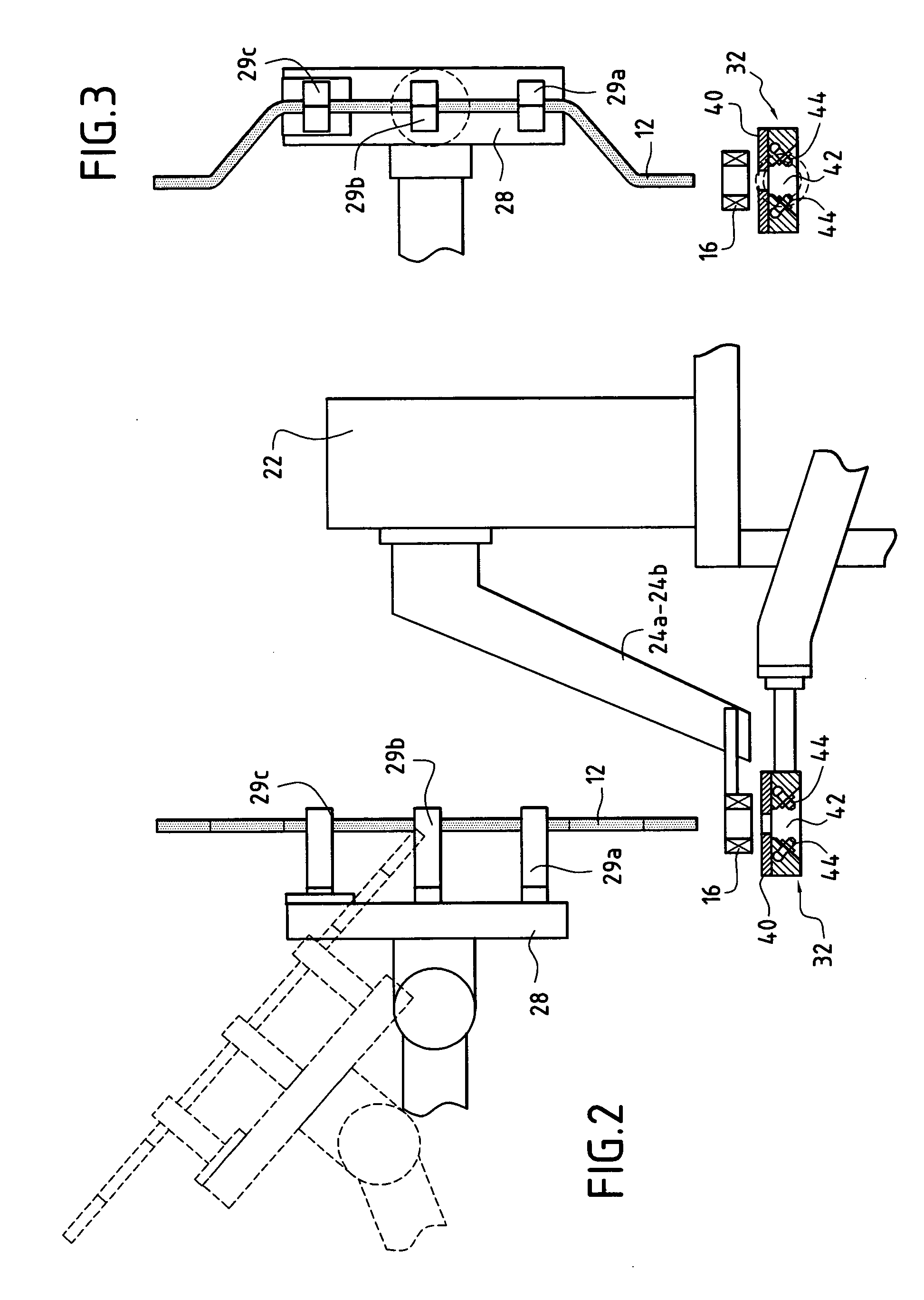
[0021] In a preferred embodiment, the cooling means may comprise a shower of annular structure dimensioned to allow the element to pass therethrough, and located immediately downstream from the induction coil. This makes it possible to obtain quenching quite quickly. Under such circumstances, the induction coil is preferably substantially horizontal. In this way, the shower can be placed beneath the coil and in the immediate vicinity thereof, with the jets of cooling fluid being directed towards the element and downwards so as to minimize the risk of drops of liquid splashing into the heating zone defined by the coil.
[0022] As explained below, it is particularly advantageous for the cooling to take place quite quickly after localized induction heating. It is therefore advantageous for the shower to be placed close to the coil. It may be carried by a second multi-axis robot operating synchronously with the first robot, thus enabling its position and its orientation to be varied as a function of the shape of the element to be treated, while holding it as close as possible to the induction coil, but without interfering therewith.
[0024] If the element is made from a solid metal bar that has been bent, it is advantageous to implement surface quenching so as to obtain an outer zone of martensitic structure and a core zone of ferrito-pearlitic structure. These two zones are separated by a transition zone of relatively small and well-controlled thickness. It is found that the effect of surface quenching a solid bar is to create compression stresses therein, thereby considerably increasing the ability of the treated zone to withstand fatigue.
[0025] When the suspension component is made out of a tubular metal bar, quenching is performed to a depth suitable for ensuring that a martensitic structure is created throughout the thickness of the wall of the tubular bar. The consequence of the treatment is to improve the crystalline structure of the metal so as to obtain good ability to withstand fatigue. Thereafter the inside of the tubular bar can be subjected to shot-blasting, thereby introducing compression stresses inside the structure of the hollow bar in a different manner, said means being known per se for improving the ability of the treated portion to withstand fatigue. It is preferable to perform shot-blasting of the inside freely by injecting shot directly into one end.

Problems solved by technology

The problem of determining ability to withstand fatigue with such elements is becoming ever more critical, mainly because of two trends:
Also, weight reduction due to the use of a tubular bar leads (compared to a solid bar and for identical amplitude of movement) to an increase of strain.
It is accepted that this method of hot-bending followed by overall quenching does not enable highly-stressed bars to be produced.
Quenching the bar leads to a martensitic transformation to the core of the bar, providing the steel was caused to be completely austenitic during the conduction heating stage.
That method is slow and expensive.
Such a method has been found to be extremely slow and difficult to perform because of the electrical losses that occur in the flexible connection powering the moving inductor.
In that method, the bar is quenched throughout, thereby making it more difficult to forge its ends since forging then needs to be performed hot.

Method used


Image

  • Induction quenching installation, in particular for fabricating suspension components
  • Induction quenching installation, in particular for fabricating suspension components
  • Induction quenching installation, in particular for fabricating suspension components

Examples


Embodiment Construction

[0032] The installation 11 as shown is more particularly designed for applying heat treatment by localized induction heating of an elongate metal element 12 which, in the example shown, is an anti-roll bar of a motor vehicle suspension system. At this stage of fabrication, this element is in the form of a solid cylindrical bar of steel which has been preformed cold using a conventional technique. As described below, the same installation can be used for applying heat treatment to a hollow bar or to an active half-bar, etc . . . . The element for treatment is fabricated in this case from a cylindrical bar of lightly-alloyed steel. After being shaped cold, this element is subjected to surface quenching implemented by the installation shown. At the end of this surface quenching, the portions of the element that have been surface quenched are constituted by a surface zone of martensitic structure and a core zone that is ferrito-pearlitic, these two zones being united via a transition zo...


PUM

PropertyMeasurementUnit
Thicknessaaaaaaaaaa
Structureaaaaaaaaaa

Abstract

A thermal quenching installation making use of induction heating. This installation has induction heater means comprising a stationary induction coil, handling means to cause the element to pass through said coil, and cooling means, preferably a shower, disposed downstream from the coil.

Description

[0001] The invention relates to a thermal quenching installation for treating an elongate metal element, such as in particular a suspension component for a motor vehicle, e.g. an anti-roll bar, an active half-bar, etc.[0002] The invention applies most particularly to heat treatment for an element that needs to present good resistance to fatigue, i.e. in use, it must be capable of withstanding repeated forces in particular in twisting and / or bending. The invention relates more particularly to a novel installation for performing thermal quenching by induction heating. The invention also provides a method of fabricating a metal element, the method including such a thermal quenching step.[0003] In the automotive industry, certain components of the suspension system need to be capable of withstanding repeated stresses during their lifetime. When designing such a component, various treatments are specified for increasing its ability to withstand fatigue. In order to evaluate the effective...

Claims


Application Information

Patent Timeline
IPC IPC(8): C21D1/10C21D1/42C21D1/62C21D9/00C21D9/08
CPCC21D1/10C21D1/42C21D9/0018C21D9/0068C21D2221/10Y02P10/25
Inventor LECOESTER, FRANCOIS
Owner ALLEVARD REJNA AUTOSUSPENSIONS
Learn More