Control apparatus and method for lock-up clutch of vehicle

a technology for controlling apparatus and lock-up clutch, which is applied in the direction of fluid gearings, dynamo-electric gear control, gearings, etc., can solve the problems of reducing fuel efficiency, wasting engine resources, and not necessarily providing a sufficiently high fuel efficiency of known slip control devices

Inactive Publication Date: 2004-11-18
TOYOTA JIDOSHA KK
View PDF9 Cites 39 Cited by
  • Summary
  • Abstract
  • Description
  • Claims
  • Application Information

AI Technical Summary

Benefits of technology

[0006] With the known slip control device for the lock-up clutch as described above, the lock-up clutch is normally placed in a released state for prevention of engine stall when the vehicle is stopped, and is also placed in a released state so as to increase the engine speed and improve starting and accelerating capabilities of the vehicle when the vehicle at rest is started. Where the hydraulic power transmitting device is in the form of a torque converter, the torque converter functions to amplify torque in a torque conversion range thereof, thus assuring further improved accelerating capability upon a start of the vehicle.
[0011] According to a second aspect of the invention, there is provided a control apparatus for controlling a lock-up clutch of a vehicle having (a) a hydraulic power transmitting device equipped with the lock-up clutch for directly coupling an input rotary member with an output rotary member, and (b) an automatic transmission operatively coupled to an output side of the hydraulic power transmitting device equipped with the lock-up clutch, for establishing a selected one of a plurality of gear stages by changing a combination of operating states of a plurality of hydraulic friction devices, which apparatus comprises (1) a neutral control unit that places at least one of the hydraulic friction devices for releasing a power transmission path in the automatic transmission in a released state or a slipping state when the vehicle is stopped, and (2) an original pressure control unit that raises an original pressure of the above-indicated at least one hydraulic friction device by a predetermined level during neutral control of the neutral control unit, and gradually reduces the original pressure after the neutral control is finished.
[0012] With the control apparatus as described above, the hydraulic friction device for releasing the power transmission path of the automatic transmission is placed in a released or slipping state by the neutral control unit when the vehicle is stopped. Also, when the neutral control for placing the hydraulic friction device in a slipping state is finished, the original pressure of the hydraulic friction device that has been raised by the predetermined value is gradually reduced and returned to a value established prior to the neutral control. When slip starting control for starting the vehicle while slipping the lock-up clutch is performed immediately after the neutral control, therefore, a rapid change in the original pressure used for slip control of the lock-up clutch is avoided, and slip control is favorably carried out without suffering from torque fluctuations due to such a rapid change in the original pressure.

Problems solved by technology

Thus, the known slip control device does not necessarily provide a sufficiently high fuel efficiency.
For example, if torque that is larger than the torque capacity of the hydraulic power transmitting device is to be transmitted from the engine to the device, the torque is only used for an increase or rise of the engine speed, and thus the power of the engine is wastefully consumed, resulting in a reduction in the fuel efficiency.

Method used


Image

  • Control apparatus and method for lock-up clutch of vehicle
  • Control apparatus and method for lock-up clutch of vehicle
  • Control apparatus and method for lock-up clutch of vehicle

Examples


Embodiment Construction

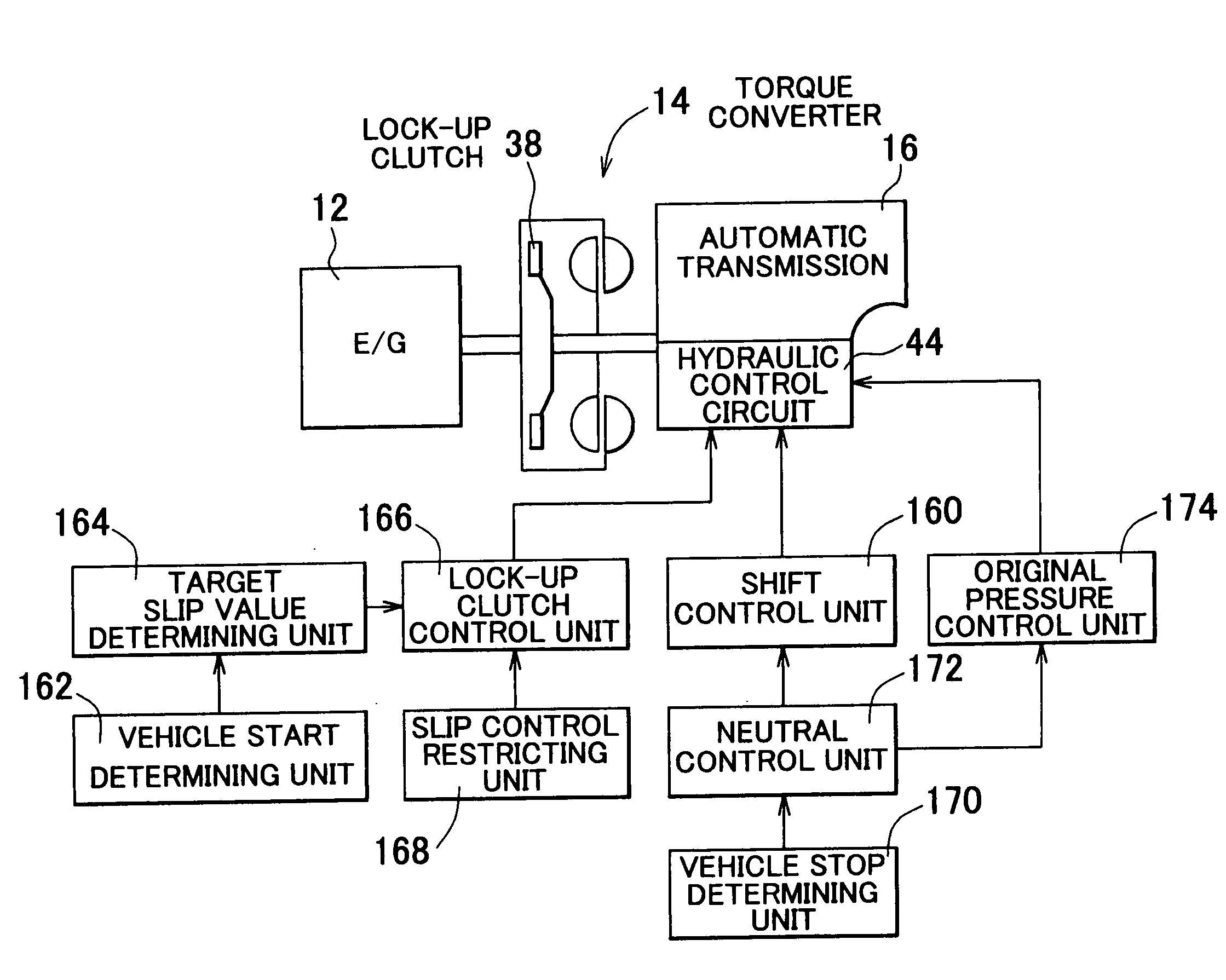
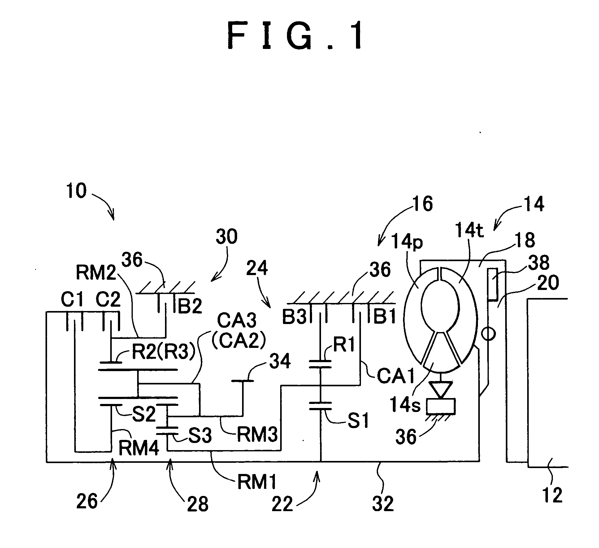
[0030] An exemplary embodiment of the invention will be described in detail with reference to the drawings. FIG. 1 schematically shows a driving system 10 of a vehicle, which employs a control apparatus according to one embodiment of the invention. The driving system 10, which is suitably employed in a FF (front engine front drive) vehicle, includes a transversely-mounted automatic transmission 16 and an engine 12 as a power source for running the vehicle. The power of the engine 12 in the form of an internal combustion engine is transmitted to right and left driving wheels, via a torque converter 14 that functions as a hydraulic power transmitting device, automatic transmission 16, a differential gear unit (not shown) and a pair of axles.

[0031] The torque converter 14 includes a pump impeller 14p coupled to a crankshaft of the engine 12, a turbine wheel 14t coupled to an input shaft 32 of the automatic transmission 16, and a stator 14s coupled to a transmission case 36 via a one-wa...


PUM


Abstract

In a vehicle having a hydraulic power transmitting device equipped with a lock-up clutch on an output side of the engine, a control apparatus for controlling the lock-up clutch is provided which includes a lock-up clutch control unit that places the lock-up clutch in a slipping state when the vehicle is started so that torque received from the engine is transmitted to a later-stage transmission via the lock-up clutch as well as the hydraulic power transmitting device.

Description

INCORPORATION BY REFERENCE[0001] The disclosures of Japanese Patent Application Nos. 2003-139551 filed on May 16, 2003 and 2004-79074 filed on Mar. 18, 2004, each including the specification, drawings and abstract, are incorporated herein by reference in their entireties.[0002] 1. Field of the Invention[0003] The invention generally relates to an apparatus and a method for controlling a lock-up clutch of a vehicle, and, more particularly, to a technique for transmitting a part of torque generated from an engine to a later-stage transmission via a lock-up clutch as well as a hydraulic power transmitting device when the vehicle is started, thus assuring further improved fuel economy of the vehicle.[0004] 2. Description of Related Art[0005] In a known type of a vehicle, a hydraulic power transmitting device is provided which includes a lock-up clutch for directly coupling input and output rotary members of the device, and output torque of the engine is transmitted to an input shaft of ...

Claims


Application Information

Patent Timeline
Patent Type & Authority Applications(United States)
IPC IPC(8): F16H59/36F16H59/46F16H59/54F16H61/14
CPCF16H59/36F16H59/54F16H61/143F16H2059/467Y10T477/78F16H2059/183F16H2059/363F16H2061/145Y10T477/755F16H2312/02
Inventor OSHIMA, KOJIKIMURA, HIROMICHITAKEUCHI, HIROAKIWATANABE, KAZUYUKIKONDO, TAKAHIROAYABE, ATSUSHIKAWAMURA, TATSUYASAGAWA, AYUMUSUGIMURA, TOSHIOOKUDA, KOICHI
Owner TOYOTA JIDOSHA KK
Why Eureka
Try Eureka