Display device and electronic equipment

a display device and electronic equipment technology, applied in the field of display devices, can solve problems such as preventing the thin shape of the display device, and achieve the effect of not reducing the resolution

Active Publication Date: 2004-12-02
SEMICON ENERGY LAB CO LTD
View PDF10 Cites 86 Cited by
  • Summary
  • Abstract
  • Description
  • Claims
  • Application Information

AI Technical Summary

Benefits of technology

0027] In view of the aforementioned problems, it is an object of the present invention to provide a display device that is able to display a th...

Problems solved by technology

Since the light-emitting element itself emits light, it is unnecessary to provide a light source unlike the case of using a liquid crystal panel.
Therefore,...

Method used


Image

  • Display device and electronic equipment
  • Display device and electronic equipment
  • Display device and electronic equipment

Examples


embodiment

[0128] (Embodiment Mode 4)

[0129] Next, an explanation will be given for switching of a scanning direction and a video signal in switching from a two-dimensional image to a three-dimensional image or from a three-dimensional image to a two-dimensional image.

[0130] In general, in a panel that has a plurality of pixels arranged in a matrix shape, a line of pixels are selected and video signals are input. A driving method of inputting video signals in sequence into the selected line of pixels is referred to as dot-sequential driving. In addition, a driving method of inputting video signals at once into all of the line of pixels is referred to as line-sequential driving. In any driving method, a video signal to be input to each pixel always has image information corresponding to the pixel.

[0131] FIG. 8(A) shows a panel that has a plurality of pixels provided in a matrix shape and image information (D1 to D35) input to each pixel. It is assumed that the panel shown in FIG. 8(A) is driven ...

embodiment 1

[0146] [Embodiment 1]

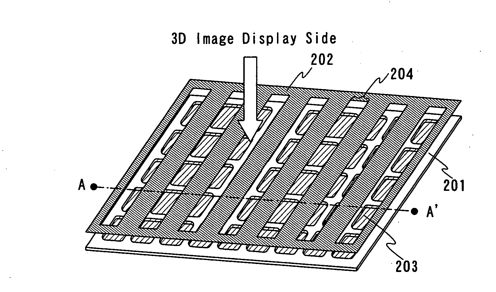
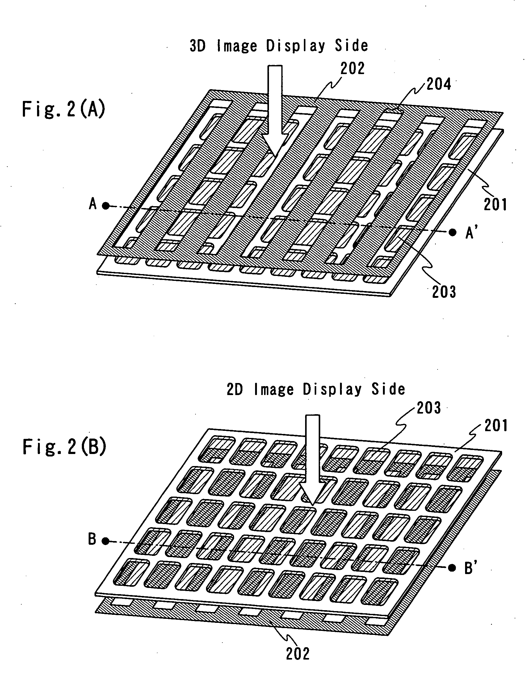
[0147] In the present embodiment, of optical systems for controlling a traveling direction of light from a pixel, structures of a lenticular lens and a microlens array (fly's-eye lens) will be described.

[0148] FIG. 10(A) shows a perspective view of a lenticular lens. The lenticular lens has a shape like a plurality of hog-backed lenses connected, and light is condensed at a convex portion in the shape of a half circle to control a traveling direction thereof. FIG. 11 shows a sectional view of a display device according to the present invention, which uses a lenticular lens.

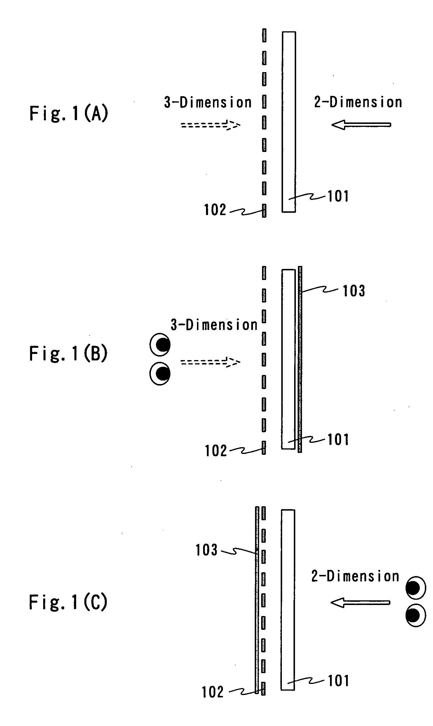
[0149] Of a plurality of pixels of a panel 1101, FIG. 11 shows a line of pixels 1104 in the direction along a line connecting both eyes. In addition, reference numeral 1102 denotes a lenticular lens, and hog-backed convex portions have a longitudinal direction that corresponds to a direction vertical to the direction along the line connecting the both eyes in a plane parallel to the panel 1101...

embodiment 2

[0156] [Embodiment 2]

[0157] The present embodiment will describe structures of a signal line driver circuit and a scan line driver circuit in an active matrix display device according to the present invention, which have a function of switching a scanning direction.

[0158] FIG. 12 shows a circuit diagram of a signal line driver circuit according to the present embodiment. The signal line driver circuit shown in FIG. 12 corresponds to analog video signals. In FIG. 12, reference numeral 1201 denotes a shift register, which generates a timing signal that determines the timing of sampling a video signal in accordance with a clock signal CK, an inversion clock signal CKb by inverting the clock signal CK, and a start pulse signal SP.

[0159] In addition, in the shift register 1201, a plurality of flip-flop circuits 1210 and a plurality of transmission gates 1211 and 1212, of which two correspond to each flip-flop circuit 1210, are provided. Switching of the transmission gates 1211 and 1212 i...


PUM


Abstract

It is an object of the present invention to provide a display device that is able to display a three-dimensional image without reducing resolution in displaying a two-dimensional image to half, and prevent the device itself from being bulky. This display device is a display device that has a light-emitting device having a plurality of pixels and an optical system at one side of the light-emitting device, where the light-emitting element has two electrodes that both have translucency, light is shielded by the first shield means and light is shielded by the second shield means, and the optical system makes light emitted from one of two adjacent pixels of the plurality of pixels incident into a let eye of a viewer and makes light emitted from the other incident into a right eye of the viewer by controlling a traveling direction of light emitted from the plurality of pixels.

Description

TECHINCAL FIELD[0001] The present invention relates to a display device that uses a light-emitting device that is able to switch between a two-dimensional image display and a three-dimensional image display. The light-emitting device includes a panel that has a light-emitting element sealed and a module that has a circuit, such as an IC including a controller, mounted on the panel. The present invention further relates to an electronic equipment that uses the display device.[0002] When a difference in retinal image between both eyes (binocular parallax), which is probably generated when an object is watched with both eyes, is nonrandomly produced in a display device, it is possible to make human eyes recognize a three-dimensional image. Various display devices for a three-dimensional image, which use this principle of binocular parallax, have been developed. The display devices for a three-dimensional image are broadly classified into a type with specific spectacles for binocular vi...

Claims


Application Information

Patent Timeline
IPC IPC(8): G02B30/25G02B30/27G02B30/30H04N13/305H04N13/307
CPCG02B27/2214G02B27/2228H04N13/0454H04N13/0406H04N13/0409H04N13/0404H04N13/305H04N13/31H04N13/359H04N13/307G02B30/34G02B30/27G02B30/30G03B35/24
Inventor MIYAGAWA, KEISUKEKIMURA, HAJIME
Owner SEMICON ENERGY LAB CO LTD
Why Eureka
Try Eureka