Electro-kinetic air transporter and conditioner devices with enhanced arching detection and suppression features

a technology of air transporter and conditioner, which is applied in the direction of emergency protective arrangements for limiting excess voltage/current, electric supply techniques, disinfection, etc., can solve the problems of device bulkiness, device size and bulk of a small filing cabinet, and device cumbersomeness, so as to minimize the resistance of the focus electrode and enhance the air flow

Inactive Publication Date: 2004-12-16
PANASONIC PRECISION DEVICES
View PDF98 Cites 29 Cited by
  • Summary
  • Abstract
  • Description
  • Claims
  • Application Information

AI Technical Summary

Benefits of technology

0098] In one embodiment, the electrodes assembly 220 has a focus electrode(s). The focus electrodes can produce an enhanced air flow exiting the devices. The focus electrode can have a shape that does not have sharp edges manufactured from a material that will not erode or oxides existing with steel. In one embodiment, the diameter of the focus electrode is 15 times greater than the diameter of the first electrode. The diameter of the focus electrode can be selected such that the focus electrode does not function as an ion generating surface. In one embodiment, the focus electrodes are electrically connected to the first array 230. Focus electrodes help direct the air flow toward the second electrode for guiding it towards particles towards the trailing sides of the second electrode.
0099] The focus electrodes can be "U" or "C" shaped with holes extending there through to minimize the resistance of the focus electrode on the air flow

Problems solved by technology

Often these devices are somewhat cumbersome, and have the size and bulk of a small filing cabinet.
Although such fan-powere

Method used


Image

  • Electro-kinetic air transporter and conditioner devices with enhanced arching detection and suppression features
  • Electro-kinetic air transporter and conditioner devices with enhanced arching detection and suppression features
  • Electro-kinetic air transporter and conditioner devices with enhanced arching detection and suppression features

Examples


Embodiment Construction

of Air-Transporter-Conditioner System with Germicidal Lamp

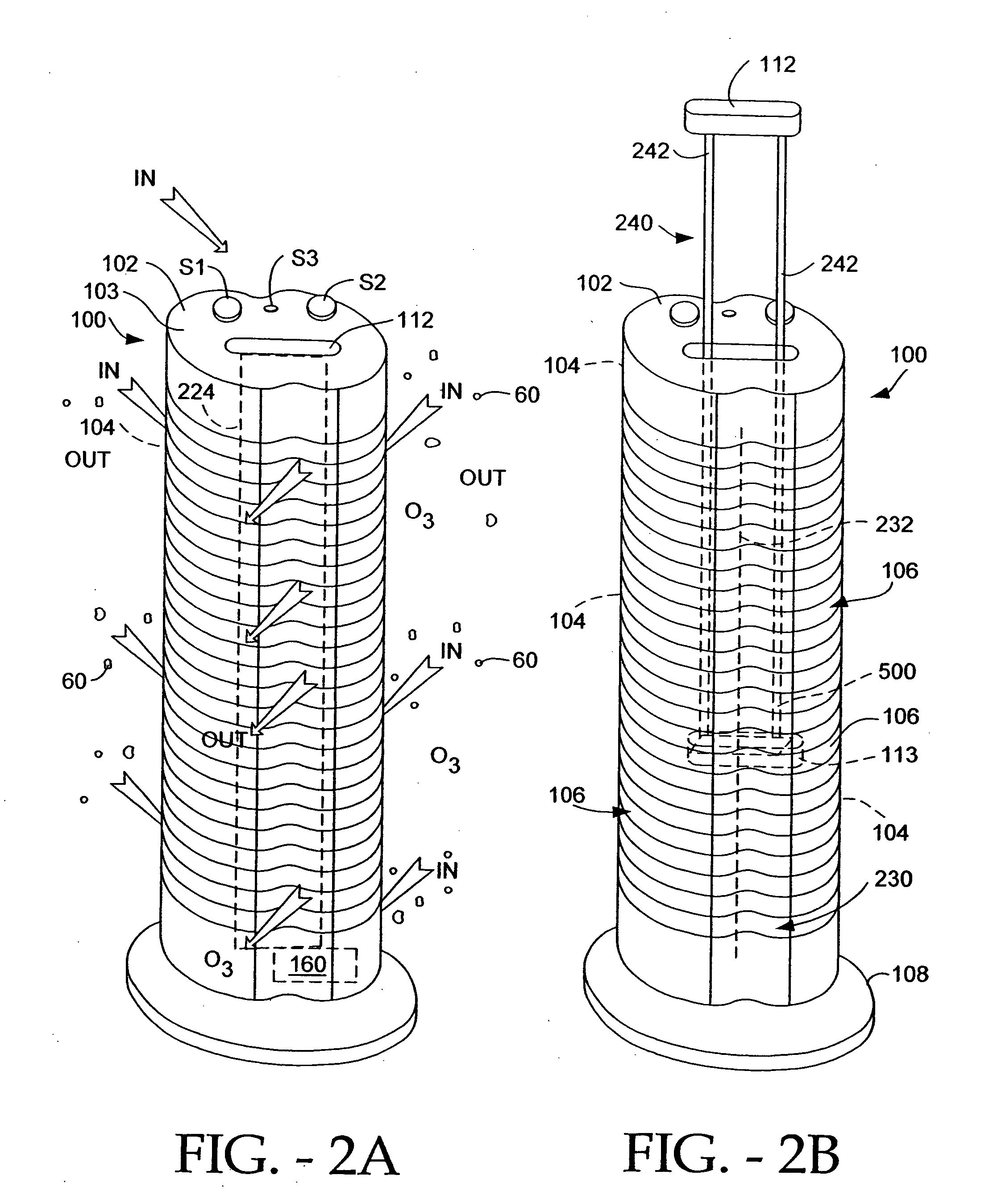
[0026] FIGS. 3A-6 depict various embodiments of the device 200, with an improved ability to diminish or destroy microorganisms including bacteria, germs, and viruses. Specifically, FIGS. 3A-6 illustrate various preferred embodiments of the elongated and upstanding housing 210 with the operating controls located on the top surface 217 of the housing 210 for controlling the device 200.

[0027] FIGS. 3A-3E

[0028] FIG. 3A illustrates a first preferred embodiment of the housing 210 of device 200. The housing 210 is preferably made from a lightweight inexpensive material, ABS plastic for example. As a germicidal lamp (described hereinafter) is located within the housing 210, the material must be able to withstand prolonged exposure to class UV-C light. Non "hardened" material will degenerate over time if exposed to light such as UV-C. By way of example only, the housing 210 may be manufactured from CYCLOLAC.RTM. ABS Resin, (material d...


PUM


Abstract

Systems and methods are provided for monitoring and suppressing arcing between a first electrode and a second electrode of an electro-kinetic system. A current (or voltage) associated with the electro-kinetic system is monitored in order to adjust a first count and a second count. Each time a monitored value reaches a threshold, the first count is incremented. Each time the first count reaches a first count threshold, the electro-kinetic system is temporarily shut down for a predetermined period, the second count is incremented, and the first count is re-initialized. The electro-kinetic system restarts after the predetermined period. When the second count reaches a second count threshold, the electro-kinetic system is shut-down until a reset condition is satisfied.

Description

PRIORITY CLAIM[0001] This application claims priority under 35 U.S.C. 119(e) to U.S. Provisional Patent Application No. 60 / 477,980, filed Jun. 12, 2003, entitled "ELECTRO-KINETIC AIR TRANSPORTER AND CONDITIONER DEVICES WITH ENHANCED ARCING DETECTION AND SUPPRESSION FEATURES," which is incorporated herein by reference.[0002] This application is related to commonly assigned U.S. patent application Ser. No. 10 / 435,289, filed May 9, 2003, entitled "ELECTRO-KINETIC AIR TRANSPORTER AND CONDITIONER DEVICES WITH SPECIAL DETECTORS AND INDICATORS" (Attorney Docket No. SHPR-01028USD), which is incorporated herein by reference.[0003] The present invention relates generally to devices that transport and / or condition air.[0004] FIG. 1 depicts a generic electro-kinetic device 10 to condition air. Device 10 includes a housing 20 that typically has at least one air input 30 and at least one air output 40. Within housing 20 there is disposed an electrode assembly or system 50 comprising a first elect...

Claims


Application Information

Patent Timeline
IPC IPC(8): A61L9/015A61L9/22C01B13/11F24F1/02F24F3/16F24F11/02
CPCA61L9/015A61L9/22C01B13/11C01B13/115B03C3/68C01B2201/22C01B2201/90F24F3/166F24F2003/1682C01B2201/12F24F8/30F24F8/192Y02A50/20
Inventor TAYLOR, CHARLES E.LAU, SHEK FAIPARKER, ANDREW J.SNYDER, GREG S.MCKINNEY, EDWARD C. JR.
Owner PANASONIC PRECISION DEVICES
Why Eureka
Try Eureka