Voltage limiter

Inactive Publication Date: 2004-12-23
ABB (SCHWEIZ) AG
View PDF14 Cites 26 Cited by
  • Summary
  • Abstract
  • Description
  • Claims
  • Application Information

AI Technical Summary

Problems solved by technology

Since the connected voltage-limiting element is likewise quickly overloaded in the even

Method used


Image

  • Voltage limiter
  • Voltage limiter
  • Voltage limiter

Examples


Embodiment Construction

[0005] The invention, as it is defined in the patent claims, achieves the object of specifying a voltage limiter of the type mentioned initially, which is distinguished by a compact construction and by high reliability even in severe operating conditions.

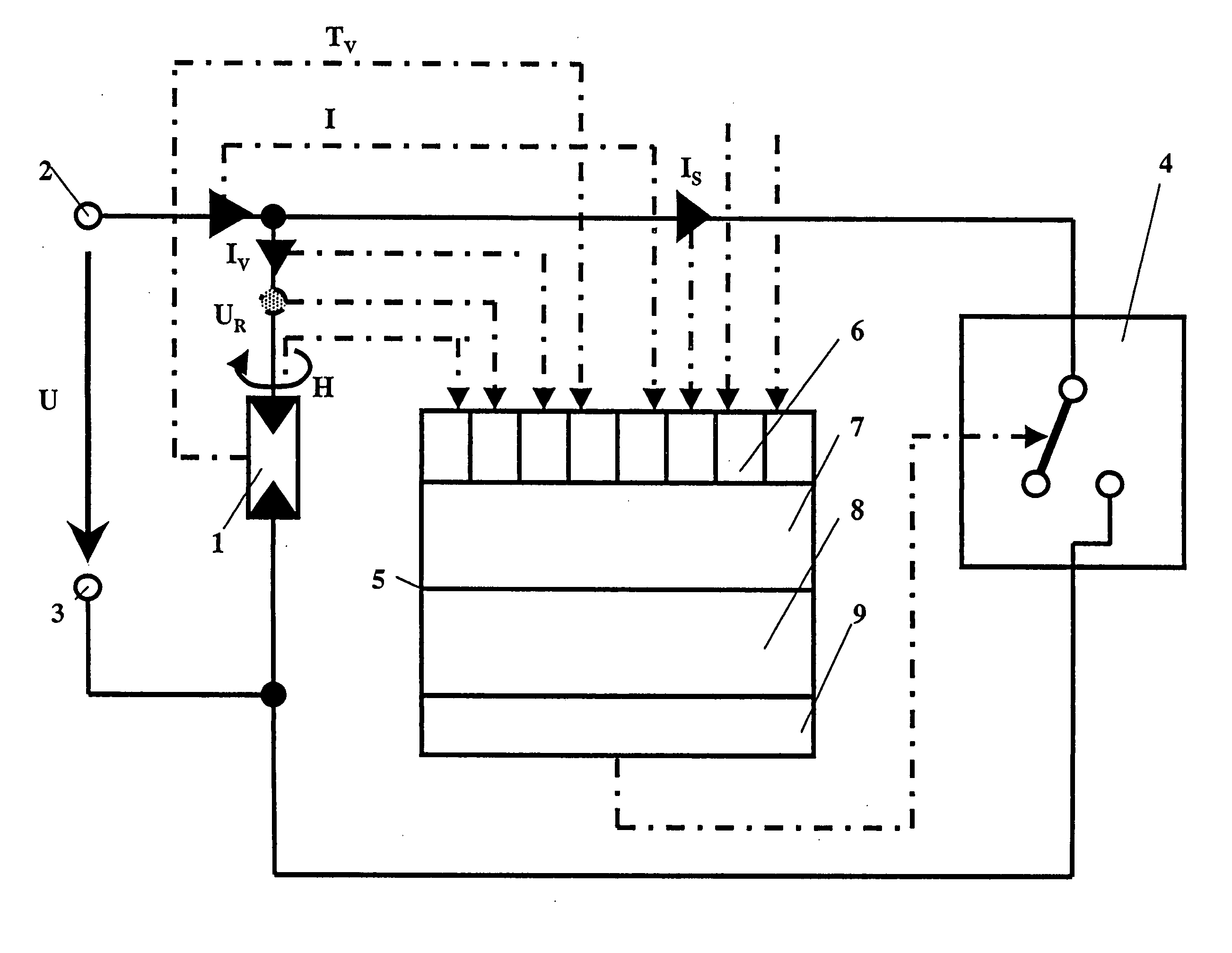
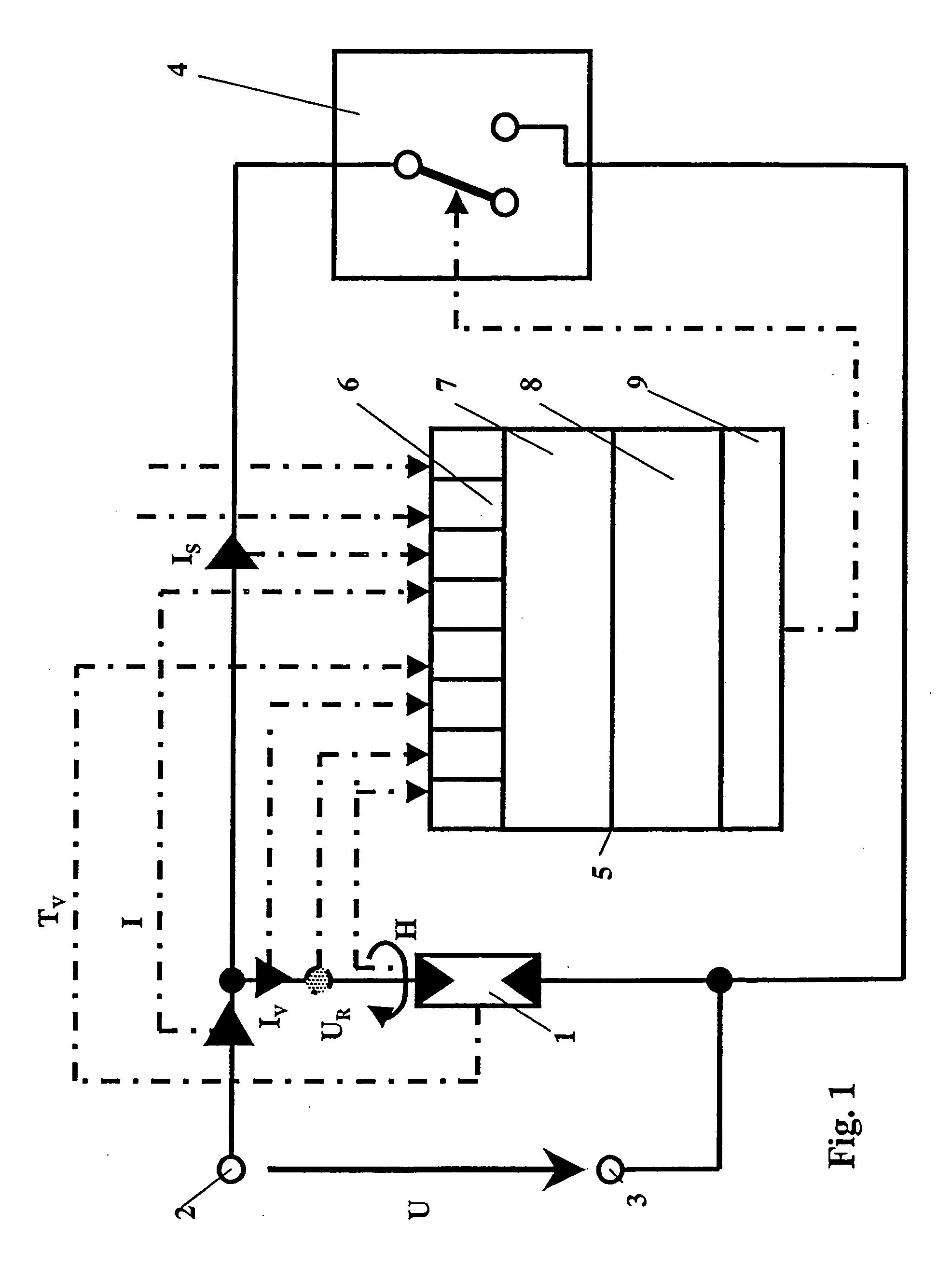
[0006] The voltage limiter according to the invention has an axially symmetrical housing with at least two areas, which are at a distance from one another in the axial direction, and of which the varistor is arranged in a first and the switching point is arranged in the second. It also contains a third area, which is at a defined potential and in which means for operating the switching point are accommodated. The arrangement of the components of the voltage limiter in separate areas results in a compact, modular construction. At the same time, this ensures that those components of the voltage limiter which are subject to power loading, namely the varistor and the switching point, are physically separated from one another, and can th...


PUM


Abstract

The voltage limiter is used to effectively limit short-term and long-term overvoltages. Said voltage limiter has a varistor (1) and a discharge path which can be connected in parallel with the varistor. The discharge path contains a switching point (4), which is preferably in the form of a semiconductor switch and can be loaded with an uninterrupted current, and which can be closed above a limit value of a signal which is dependent on an operating variable of the varistor (1). The varistor (1) is arranged in a first area (24) and the switching point (4) is arranged in a second area (26) of two areas (24, 26, 28) which are at an axial distance from one another in the direction of an axis of symmetry (20). Means (5) for operating the switching point (4) are accommodated in a third area (28), which is at a defined potential. The arrangement of the components (1, 4, 5) of the voltage limiter in separate areas (24, 26, 28) results in a compact, modular construction, and those components of the voltage limiter which are subject to power loading, namely the varistor (1) and the switching point (5), are physically separated from one another, so that they can be cooled independently of one another. Since the operating means (5), which generally operate electronically, are accommodated in an electromagnetically shielded area (28), the operational reliability of the voltage limiter is at the same time improved, and, in particular, undesirable high-energy electromagnetic interference is kept away from this area (28).

Description

[0001] The invention is based on a voltage limiter as claimed in the precharacterizing clause of patent claim 1. This voltage limiter is used to limit short-term or long-term overvoltages. The voltage limiter has a varistor and a discharge path which can be connected in parallel with the varistor. In the event of long-lasting overvoltages, a switching point which is provided in the discharge path is operated, and commutates a current, which is carried in the varistor when limiting overvoltages, into the discharge path.PRIOR ART[0002] The precharacterizing clause of the invention refers to a prior art for voltage limiters as is described in U.S. Pat. No. 4,068,281 A. The described limiting apparatus has a varistor 10, in parallel with which a discharge path with a semiconductor switch 16 is connected. When a long-lasting overvoltage occurs, the varistor carries current which, after a time delay which can be predetermined, is commutated into the discharge path by short-circuiting the ...

Claims


Application Information

Patent Timeline
IPC IPC(8): H02H1/00H01C1/06H01C7/12H02H9/04H05K9/00
CPCH02H9/042H02H9/043
Inventor ZELLER, PETERSCHIETZSCH, FALKOBARLAGE, JUTTA
Owner ABB (SCHWEIZ) AG
Why Eureka
Try Eureka