Multi standard transceiver architecture for wlan

a transceiver and multi-standard technology, applied in the field of multi-standard transceiver architecture for wlan, can solve the problem of slow data rate for wlan

Inactive Publication Date: 2004-12-23
FIRSTPASS SEMICON AB
View PDF9 Cites 47 Cited by
  • Summary
  • Abstract
  • Description
  • Claims
  • Application Information

AI Technical Summary

Benefits of technology

[0003] An object of the present invention is thus to attain a method and apparatus by which it is possible to implement a transceiver architecture for smooth transition from existing 2.4 GHz WLAN systems to 5 GHz WLAN systems.
[0011] By utilizing the radio front end transceiver according to the invention, it is possible to implement a transceiver architecture with a maximum of hardware share to minimize power consumption, die area and manufacturing cost for smooth transition from existing 2.4 GHz WLAN systems to 5 GHz WLAN systems.
[0012] According to an embodiment of the invention, a radio frequency synthesizer is arranged to utilize fixed local oscillator frequencies to convert signals in the radio frequency bands to overlapping intermediate frequency bands in the receive paths. The radio frequency synthesizer is implemented by means of a digital phase locked loop. The digital phase locked loop has a programmable divider to select the required local oscillator frequency for the desired radio frequency band. The radio frequency synthesizer is also utilized for the transmitter paths to up convert the intermediate frequency bands to the desired radio frequency bands. By employing the radio frequency synthesizer in both the receive and transmit paths, hardware share is obtained, the size of the radio front end transceiver can be decreased and the manufacturing cost can be reduced.
[0013] According to another embodiment of the invention, an intermediate frequency synthesizer generates local oscillator frequencies with a unit step size to convert a specific channel from the intermediate frequency band to baseband. The intermediate frequency synthesizer is implemented by means of a digital phase locked loop. A programmable divider of the phase locked loop is set to convert the specific channel to baseband. Depending on the standards for which the transceiver according to the invention is to be used, the channel bandwidths will vary. The unit step size of the intermediate frequency synthesizer is chosen in accordance with the bandwidth of the most narrow channel. By employing this type of intermediate frequency synthesizer, the number of intermediate frequency synthesizers used can be reduced. Again, the size of the radio front end transceiver can be decreased and the manufacturing cost can be reduced.
[0014] According to further embodiments of the present invention, image-rejection can alternatively be provided by means of antenna filtering, radio frequency band pass filtering, low noise amplifier filtering and radio frequency mixer tuning. The frequency characteristics of low noise amplifiers, commercial radio frequency band pass filters, narrow band antennas and radio frequency mixer circuitry offers image-rejection of the received radio frequency signals. This mitigates the requirements on the mixer structure of the receive paths due to the frequency planning of this architecture. An advantage of employing these components is that the number of mixers in the receive path can be reduced due to the fact that I / Q demodulation is unnecessary. As a consequence, neither is it necessary to match the receiver radio frequency path before I / Q demodulation, nor does the radio frequency mixer have to be quadrature and radio frequency signal routing is reduced. Thus, it is possible to simplify the implementation and reduce power consumption, die area and time to market.

Problems solved by technology

The 2.4 GHz band is heavily occupied with the other standards, which causes great interference leading to slower data rate for WLAN.
However, this transition will not occur overnight and therefore a problem is that during the transition, WLANs must be able to handle both of the above mentioned frequency bands.

Method used


Image

  • Multi standard transceiver architecture for wlan
  • Multi standard transceiver architecture for wlan
  • Multi standard transceiver architecture for wlan

Examples


Embodiment Construction

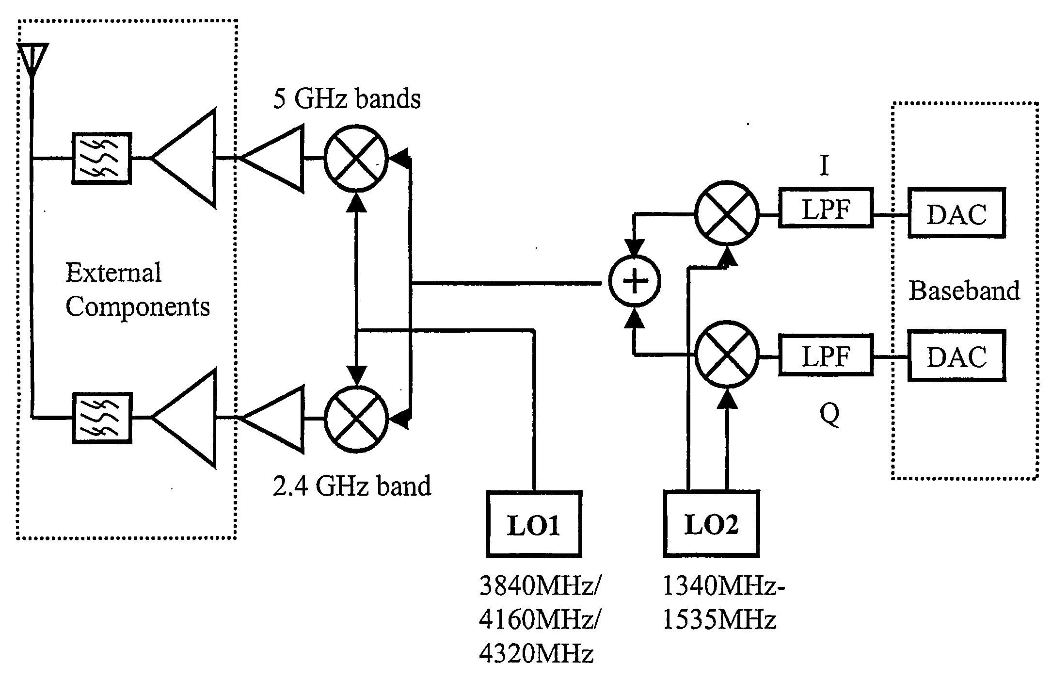
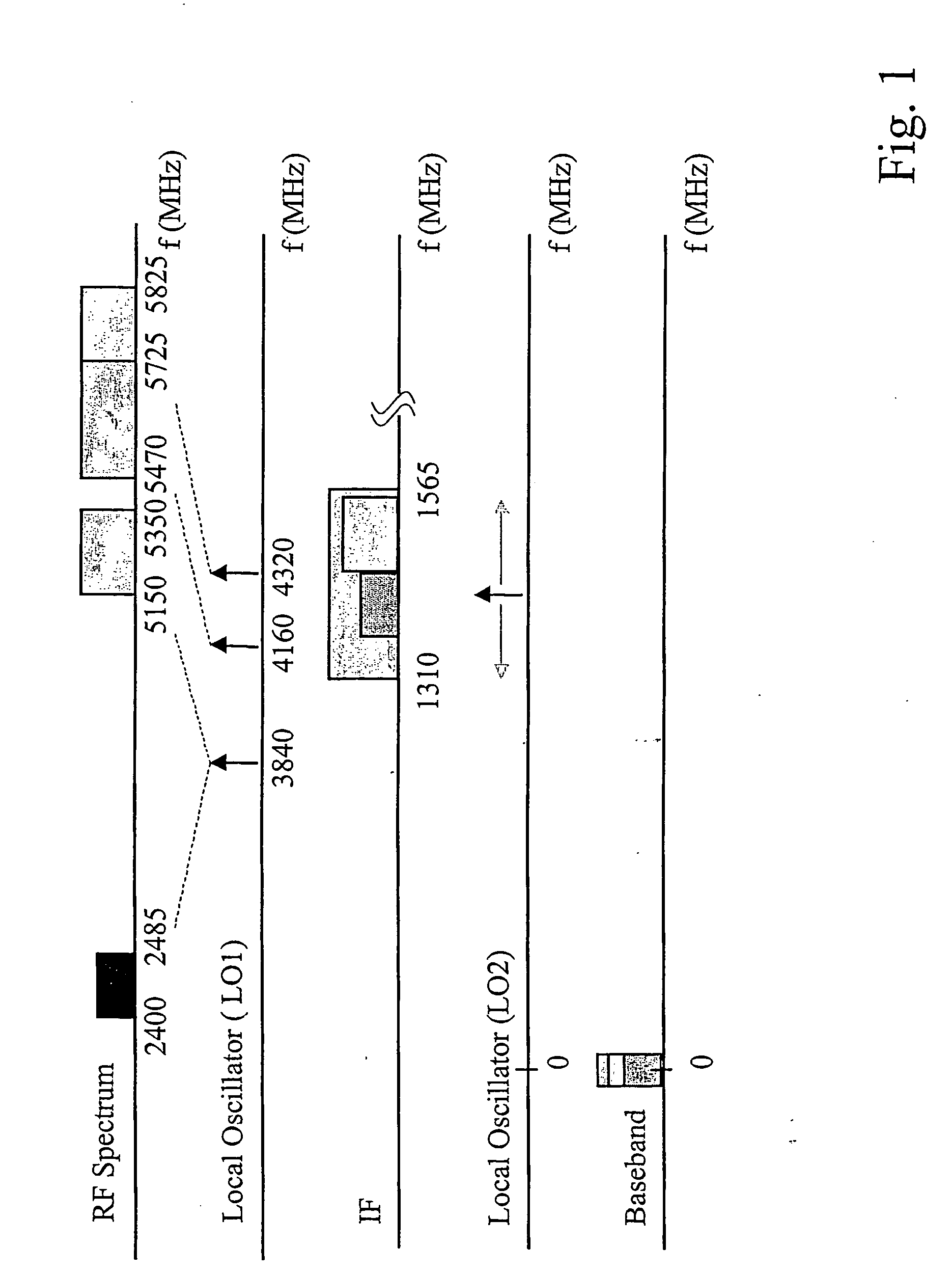
[0028] The frequency plan is an important aspect of the architecture according to the present invention. A great deal of hardware reuse leading to lower power consumption and smaller die area is achieved by careful frequency planning. The frequency plan according to FIG. 1 is constructed to cover the currently existing RF bands of the standards mentioned above. Thus, according to an embodiment of the transceiver of the present invention there is provided a tri-band architecture, which is summarized in the following. The first local oscillator has three distinct frequencies, 3840 MHz, 4160 MHz and 4320 MHz, to translate channels from the three RF bands to an IF frequency range between 1310 MHz-1565 MHz. The first LO frequency at 3840 MHz translates channels from 2.4 GHz RF band and 5.15-5.35 GHz RF band to the IF band. The second LO frequency at 4160 MHz translates channels from 5500 MHz-5700 MHz RF band to the IF band. The third LO frequency at 4320 MHz translates channels from 5745...


PUM


Abstract

The present invention relates to a radio front end transceiver and methods of operating the transceiver. A transceiver is employed consisting of a first and second receive path and a first and second transmit path. Each first path and second path can handle signals of a first and a second modulation format and a first and a second radio frequency band respectively. The transceiver comprises circuitry for conversion between the respective radio frequency bands and an intermediate frequency. The transceiver is arranged with intermediate frequency circuitry for conversion between the respective intermediate frequencies and basebands. At least some of the intermediate frequency circuitry is common to both receive paths and at least some of the intermediate frequency circuitry is common to both transmit paths. A frequency synthesizer is arranged to derive overlapping local oscillator frequencies suitable for use by the intermediate frequency circuitry on each of the paths.

Description

[0001] The present invention relates to a radio front end transceiver and methods of operating said radio front end transceiver.[0002] Local area networks (LANs) are being deployed extensively worldwide using a well-established copper-cable infrastructure. Wireless local area networks (WLANs) have become available as well as other emerging wireless applications in Instrumentation, Scientific and Medical (ISM) bands, including Bluetooth and HomeRF. The initial WLAN applications have used an unlicensed 2.4 GHz ISM band. The 2.4 GHz ISM band has been used for standards including cordless phones, Bluetooth, HomeRF and microwave oven in addition to WLAN. The 2.4 GHz band is heavily occupied with the other standards, which causes great interference leading to slower data rate for WLAN. An unused 5 GHz band also exists, which is cleaner and has more bandwidth to accommodate higher data throughput. There will be need to move to the 5 GHz band in the near future with increasing demand for hi...

Claims


Application Information

Patent Timeline
Patent Type & Authority Applications(United States)
IPC IPC(8): H03D7/18H04B1/40H04L12/28H04L12/56
CPCH03D7/18H04B1/005H04W88/06H04W4/18H04W84/12H04B1/406
Inventor AKTAS, ADEMRAMA, KISHOREWILSON, JAMES
Owner FIRSTPASS SEMICON AB
Why Eureka
Try Eureka