Asymmetric stent delivery system with proximal edge protection and method of manufacture thereof

a proximal edge protection and stent technology, applied in the field of intravascular catheters, can solve the problems of reducing the positive effect, requiring additional angioplasty, and crimping the stent to slip

Inactive Publication Date: 2004-12-23
BOSTON SCI SCIMED INC
View PDF62 Cites 41 Cited by
  • Summary
  • Abstract
  • Description
  • Claims
  • Application Information

AI Technical Summary

Benefits of technology

0015] A dual section enclosure or retainer such as a stepped tube is provided which comprises a first section having a first inner diameter that is connected to a second section having a second inner diameter. The first inner diameter of the first section is greater than the second inner diameter of the second section. The second inner diameter is greater than the initial outer diameter of the stent but is a close approximation thereto. The enclosure is slid over the balloon catheter so that the larger first section of the enclosure is disposed over the proximal section of the balloon and the smaller second section of the enclosure is disposed over the stent and the distal section of the balloon. Then, the balloon is partially inflated so that the proximal section of the balloon inflates and engages the larger first section of the enclosure and the stent and distal section of the balloon are prevented from substantial expansion by the smaller second section of the enclosure. The partial inflation of the stent is typically performed at a lower pressure than the pressure used for inflation of the balloon in a vascular system. The enclosure is removed thereby leaving a proximal section of the balloon with a larger d

Problems solved by technology

While angioplasty is effective in alleviating arterial stenosis in an artery or vessel, in many cases, the vessel may restenose or close down, thereby negating the positive affect of the angioplasty procedure, and possibly requiring an additional angioplasty procedure.
Frictional forces generate

Method used


Image

  • Asymmetric stent delivery system with proximal edge protection and method of manufacture thereof
  • Asymmetric stent delivery system with proximal edge protection and method of manufacture thereof
  • Asymmetric stent delivery system with proximal edge protection and method of manufacture thereof

Examples


Embodiment Construction

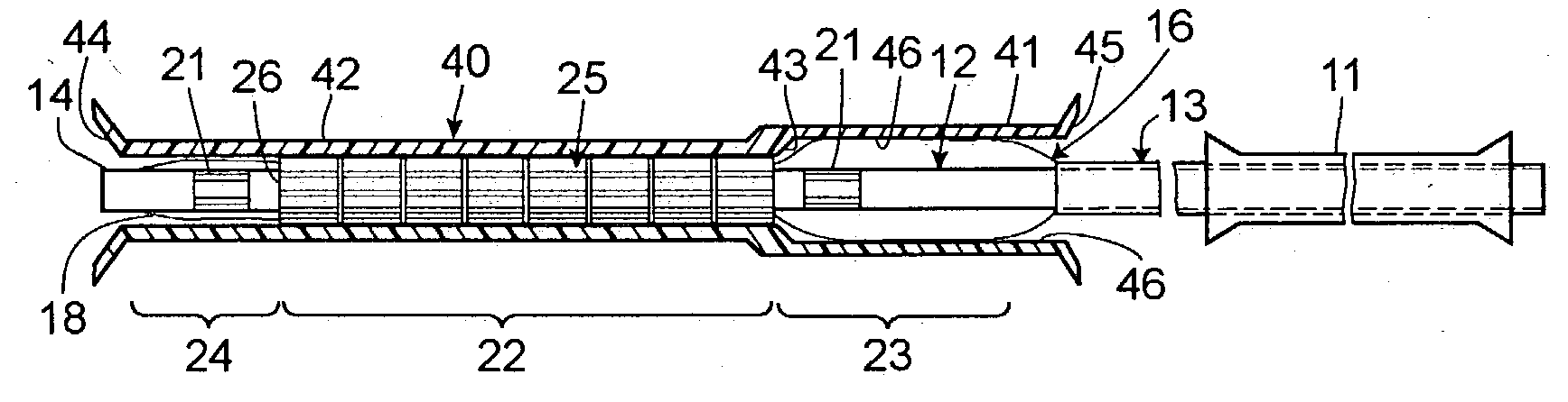
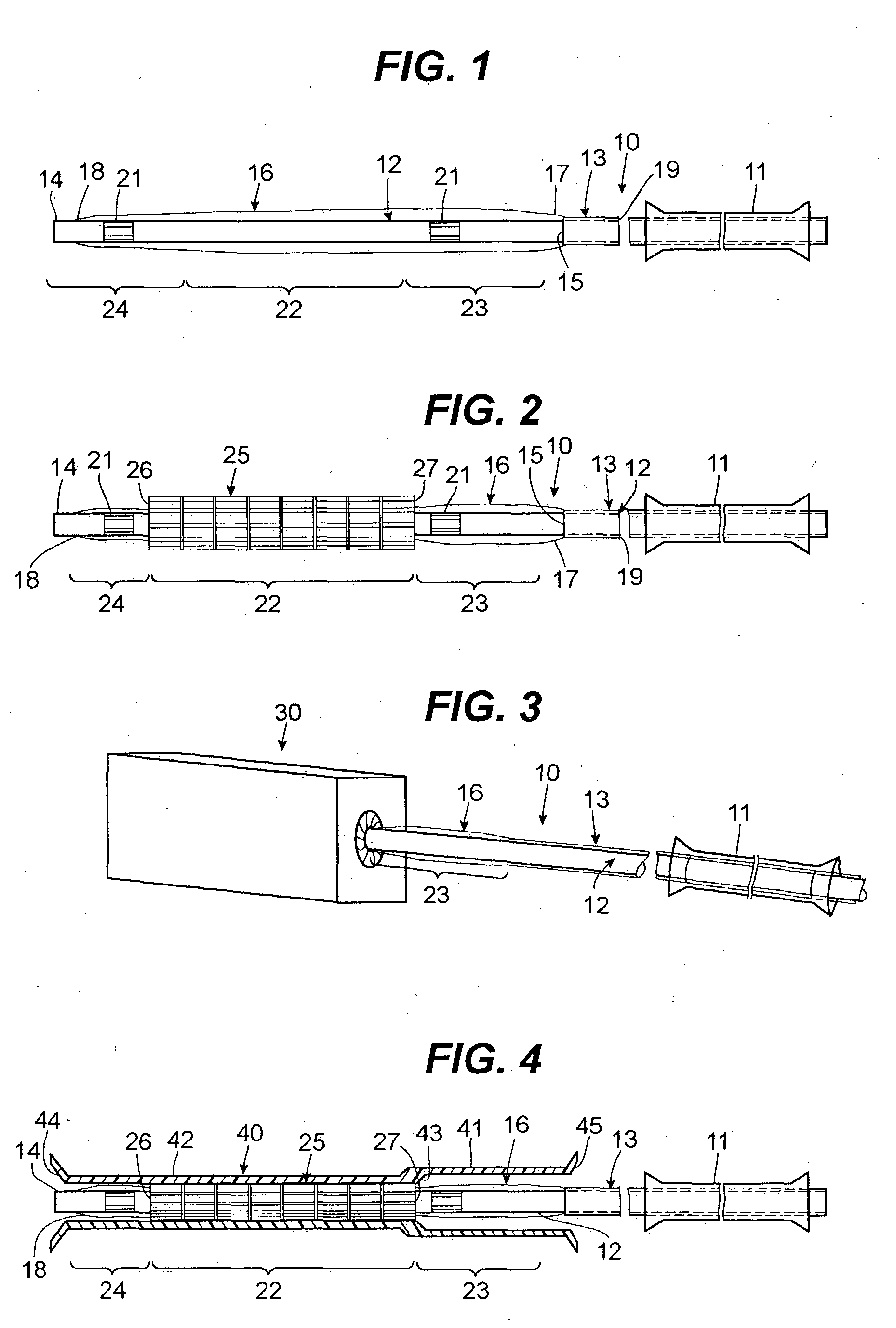
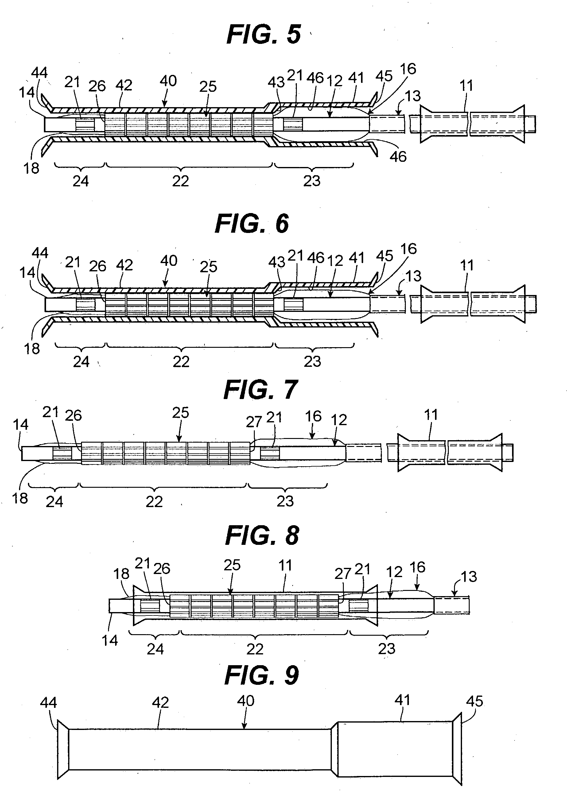
[0033] FIG. 1 illustrates a balloon catheter 10 with a protective sleeve 11 pre-loaded thereon. The balloon catheter 10 includes an inner tube 12 disposed within an outer tube 13. The inner tube 12 terminates at a distal end 14 and the outer tube 13 terminates at a distal end 15. The distal end 15 of the outer tube 13 is connected to a balloon 16 which, in turn, is also connected to the distal end 14 of the inner tube 12.

[0034] More specifically, the balloon 16 includes a proximal end 1;7 connected to the distal end 15 of the outer tube 13 and the balloon 16 further includes a distal end 18 connected to the distal end 14 of the inner tube 12. The annular gap shown at 19 between the outer tube 13 and inner tube 12 can be used for the communication of air or fluid to pressurize the balloon 16 as described below. The inner tube 12 may also be connected to one or more markers 21 for tracking the location of the balloon catheter 10 and, more specifically, the stent 25 (see FIG. 2), withi...


PUM

PropertyMeasurementUnit
Timeaaaaaaaaaa
Angleaaaaaaaaaa
Angleaaaaaaaaaa

Abstract

A balloon catheter stent deployment system is disclosed wherein a balloon catheter is provided and a tubular stent is crimped onto a distal portion of the balloon with a distal end of the stent in close proximity to a point where the distal end of the balloon is attached to the inner tube of the catheter. A proximal section of the balloon extending from a proximal end of the stent to a point where the proximal end of the balloon is attached to the outer shaft of the catheter remains uncovered by the stent and, has a larger uninflated outer diameter than the crimped stent. Thus, in some embodiments, the proximal section of the balloon provides a protective cone for the proximal end of the stent to help resist frictional forces from disengaging the stent from the balloon in the event the balloon catheter and stent are withdrawn back into a guide catheter during a procedure. A stepped enclosure is also disclosed which is used in a disclosed fabrication method to allow the proximal section of the balloon to be inflated after the stent is crimped onto the distal section of the balloon.

Description

[0001] A balloon catheter stent deployment system is disclosed which has an asymmetric longitudinal profile. In some embodiments, the configuration of the balloon allows for protection of the proximal edge of the stent in the event the stent and balloon must be withdrawn or retracted. Such a configuration can provide centering characteristics for the device. A method of manufacture of the disclosed balloon catheter stent deployment system is also disclosed as well as a tool used in the manufacture of the disclosed system.DESCRIPTION OF THE RELATED ART[0002] Intravascular catheters are widely used for a variety of diagnostic and therapeutic purposes. Specifically, angioplasty has been developed as an alternative to bypass surgery for treating vascular diseases or other conditions that occlude or reduce blood flow in a patient's vascular system. Balloon angioplasty has proven to be a useful and often a preferred treatment for coronary diseases that cause blockages, also known as steno...

Claims


Application Information

Patent Timeline
IPC IPC(8): A61F2/00A61F2/06A61F2/84A61M25/12
CPCA61F2/958A61F2002/9522Y10T29/53987A61F2250/0039A61F2002/9583A61F2/9522A61F2/9524
Inventor JAGGER, KARL A.CHRISTENSON, LINDA S.ROWE, TODDNORDIN, STANLEYNYGAARD, DANIELBEYREIS, RANDALL J.LIVINGSTON, JON
Owner BOSTON SCI SCIMED INC
Why Eureka
Try Eureka