
Method and apparatus for vaporizing and delivering reactant

a technology of reactant and vaporization, applied in chemical vapor deposition coating, coating, metal material coating process, etc., can solve the problems of destroying the self-limiting nature of deposition and contamination of solid or liquid reactants

Inactive Publication Date: 2005-01-06
ASM AMERICA INC
View PDF16 Cites 352 Cited by
  • Summary
  • Abstract
  • Description
  • Claims
  • Application Information

AI Technical Summary

Benefits of technology

[0010] It is an aim of the present invention to eliminate at least some of the drawbacks of the prior art and to provide a new method and apparatus for feeding gas phase reactants from liquid or solid sources into a vapor processing reactor.
[0012] According to another aspect of the invention, a system comprises a reactant source vessel and a reaction chamber. The reactant source vessel and the reaction chamber are positioned in separate enclosures which can be individually evacuated. The reactant source vessel and the reaction chamber are preferably thermally isolated from each other and interconnected with a first conduit comprising at least one valve. In the first conduit, the flow or diffusion of reactant from the reactant source vessel to the reaction chamber can be prevented by forming a gas phase barrier of a gas flowing in the opposite direction to the reactant flow in the conduit and the valve can be used for separating the gas spaces of the reactant source vessel and the reaction chamber during evacuation of either or both of these components. The reactant source vessel comprises at least one inlet for feeding gas into the reactant source and at least one outlet for withdrawing gas from the reactant source vessel. The outlet of the reactant source vessel communicates with the reaction chamber. In one embodiment, the gas phase barrier is formed at least partially within the enclosure surrounding the reaction chamber.
[0016] In another embodiment of the invention, an apparatus for supplying a vaporized reactant to a reaction chamber comprises a source of the vaporized reactant, a plurality of components through which the vaporized reactant flow towards the reaction chamber, and a radiant heat source for heating at least some of the plurality of components. At least one of the plurality of components is coated with a coating that reduces its reflectivity or increases its absorptivity.

Problems solved by technology

Furthermore, the solid or liquid reactant may come in contact with air during loading and maintenance operations, which may lead to contamination of the solid or liquid reactant when the vacuum of the reaction chamber is broken.
A shorter duration purge step can increase the available time for adsorption and reaction of the reactants within the reactor, but the vapor phase reactants cannot be allowed to mix at the risk of CVD reactions destroying the self-limiting nature of the deposition.

Method used


Image

  • Method and apparatus for vaporizing and delivering reactant
  • Method and apparatus for vaporizing and delivering reactant
  • Method and apparatus for vaporizing and delivering reactant

Examples


Embodiment Construction

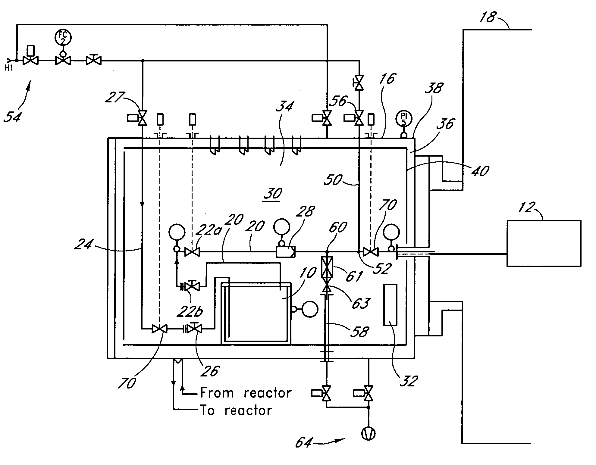
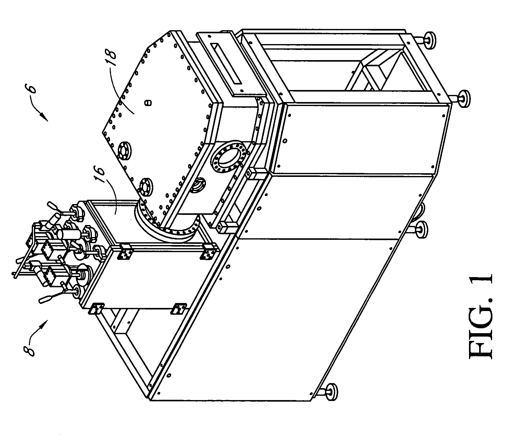
[0028]FIGS. 1-3 illustrate an exemplary embodiment of a processing system 6 comprising a reactant source apparatus 8 for feeding a gas phase reactant generated from a reactant source vessel 10 into a gas phase reaction chamber 12. A reactant (not shown), which may be liquid or solid under standard (i.e., room temperature and atmospheric pressure) conditions, is vaporized within the reactant source vessel 10, which may be maintained at or above a vaporizing temperature. The vaporized reactant is then fed into the reaction chamber 12. The reactant source vessel 10 and the reaction chamber 12 are located in a reactant source cabinet 16 and a reaction chamber vessel 18, respectively, which are preferably individually evacuated and / or thermally controlled. As will be explained in more detail below, this can be achieved by providing these components with separate cooling and heating devices, insulation and / or isolation valves and associated piping.

[0029] The exemplary reactant source app...


PUM

PropertyMeasurementUnit
Pressureaaaaaaaaaa
Pressureaaaaaaaaaa
Angleaaaaaaaaaa

Abstract

A reactant supply apparatus comprises a vessel with a gas inlet and a gas outlet. Gas lines are connected to the gas inlet or the gas outlet. A plurality of components are positioned along the gas lines. A first heating device is provided for heating the vessel. Apparatus and methods are provided for biasing the temperature of at least one of the plurality of components to a temperature higher than the vessel.

Description

REFERENCE TO RELATED APPLICATIONS [0001] This application claims the priority benefit under 35 U.S.C. § 119(e) of U.S. Provisional Application 60 / 512,931, filed May 16, 2003 and U.S. Provisional Application 60 / 537,191, filed Jan. 19, 2004.BACKGROUND OF THE INVENTION [0002] 1. Field of the Invention [0003] The present invention relates to the use of vapor phase chemical reactants. In particular, the present invention relates to feeding a vaporized reactant into a reaction chamber. [0004] 2. Description of the Related Art [0005] During semiconductor processing, various reactant gases are fed into the reaction chamber. In some applications, the reactant gases are stored in gaseous form in a reactant source vessel. In such applications, the reactant vapors are often gaseous at ambient (i.e. normal) pressures and temperatures. Examples of such gases include nitrogen, oxygen, hydrogen, and ammonia. However, in some cases, the vapors of source chemicals that are liquid or solid at ambient ...

Claims


Application Information

Patent Timeline
IPC IPC(8): C23C16/00C23C16/44C23C16/448
CPCC23C16/4402C23C16/45561C23C16/4481
Inventor SHERO, ERIC J.VERGHESE, MOHITH E.
Owner ASM AMERICA INC
Features
  • Generate Ideas
  • Intellectual Property
  • Life Sciences
  • Materials
  • Tech Scout
  • Unparalleled Data Quality
  • Higher Quality Content
  • 60% Fewer Hallucinations
Learn More