Eureka AIR delivers breakthrough ideas for toughest innovation challenges, trusted by R&D personnel around the world.

Spiral tubular tool and method

a tubular tool and spiral tube technology, applied in the direction of insulation, borehole/well accessories, construction, etc., can solve the problems of restricted expansion ability of the tube tube packer, and achieve the effect of enhancing the anchoring

Inactive Publication Date: 2005-01-06
COOK ROBERT BRADLEY +1
View PDF7 Cites 40 Cited by
  • Summary
  • Abstract
  • Description
  • Claims
  • Application Information

AI Technical Summary

Benefits of technology

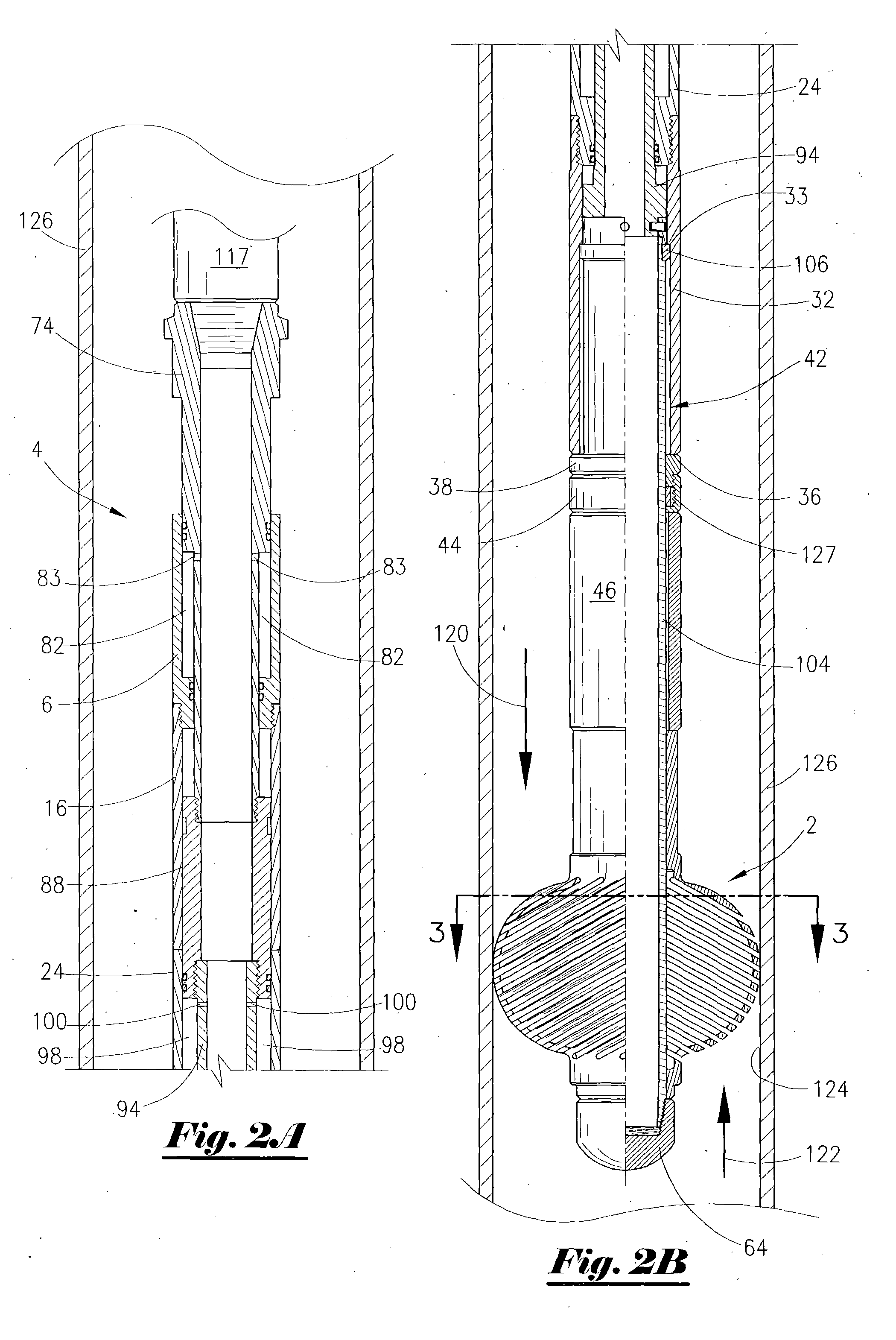
[0023] An advantage of the present invention includes the ability of the device to be used in several applications. Many different types of applications utilizing the present inventions are possible. For instance, the expandable device may be used, as previously noted, as a thru-tubing bridge plug. The expandable device could be set on electric line, wireline or it could be set on a pipe. The expandable device could be a “non-vent” wherein it is used as a platform for placement of cement / bridging type material. Alternatively, the expandable device may contain a vent valve to allow pressure movement through the center bore during cement cure.
[0024] Also, an application would be using the expandable device to locate a bottom hole assembly at a precise depth. For instance, it could be used for perforating, pressure gauges, and gravel pack assemblies, wherein the perforating guns, pressure gauges or gravel pack assemblies are hung-off the device or set on top. The expandable device may be run with or without an elastomeric member (also referred to as an elastomer). As previously noted, when run with elastomeric cover it is possible to affect a hydraulic seal. This hydraulic seal holds a liquid or gas column without the need for additional runs to place bridging material in order to seal.
[0025] Another application would be used as a thru-tubing packer with a bore through the center. For example, these types of packers could be used in production operations. Additionally, the expandable device can be run as two packers (straddled). An application using these straddle type packers would be in conjunction with operations to cover a hole in a down hole tubular. Another application using the straddle type packers would be, for instance, production tubing wherein a set of perforations is making water or other unwanted production. Cement is placed on top of the packer in the annular area. The lower zone is now produced free of unwanted production. Therefore, this is useful with multiple zones or zone with stringers of water production. Additionally, this thru-tubing expandable packer could be used to have operatively associated therewith a down hole choke, a landing profile, a flow diverter, a big bore packer, or a hanger for a velocity string, guns, gauges, or gravel pack assembly with screen, etc.
[0026] The expandable device could also be used as a thru-tubing retainer with a one-way check valve. These retainers can be used for cementing, acidizing and other types of remedial well work.
[0027] Still yet another additional application of the expandable device would be for use as a tubing stop which functions as a locator in the well. Additionally, another application with the expandable device would be as a mechanical anchor. It is possible that the outer diameter of the expandable device could be knurled before the slots are cut, or have gripping material attached. This enhances the anchoring effect that the expandable device has with the wall of the well bore. Yet another application would serve as a thru-tubing centralizer.
[0028] Another application of the present invention includes use as a casing, tubing, flow-line, or pipeline cleaner / scraper / wiper. It is possible to run the expandable device into a well, and wherein the expandable device contacts the walls of the tubular. The operator either lifts or lowers the expandable device thereby providing the cleaning function. When lifting, the work string is pulled upward. When lowering, the operator would impart a jarring impact on the device. It is possible to use the elastomeric member with this scraper device, as well as placement of bristles on the outer diameter of the expandable device. Further, it is contemplated that an application can include a hydraulic model that can be pumped through a tubular in order to clean casing, tubing, pipeline or flowline.

Problems solved by technology

As those of ordinary skill will appreciate, a small diameter tool within a larger diameter tubular may have certain limitations and disadvantages such as centralization, ability to expand, ability to engage, functionality, etc.
For instance, a thru-tubing packer, due to the initial limited size, may be restricted in its ability to expand large enough to engage, anchor and / or seal within the tubular that it is ultimately expanded within.

Method used


Image

  • Spiral tubular tool and method
  • Spiral tubular tool and method
  • Spiral tubular tool and method

Examples


first embodiment

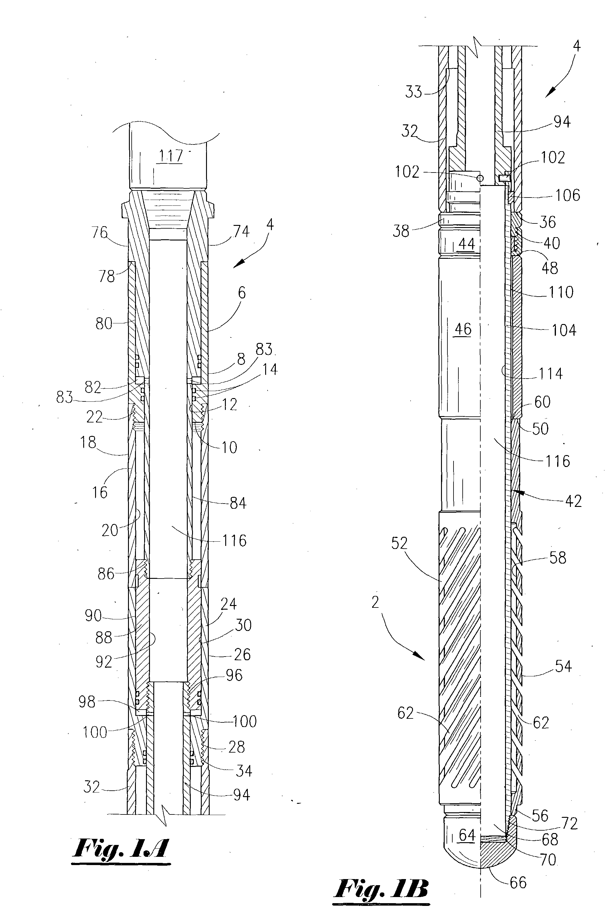
[0093] Referring now to FIG. 13, a side view of the slot pattern of the present invention will now be described. This embodiment shows the slot pattern as being slanted at a constant angle of inclination for all slots, with the cuts of the individual slots running generally parrallel to each other in a same direction. The slot pattern in FIG. 13 is referred to as a spiral pattern and is denoted by the numeral 160. In one of the preferred embodiments, the angle of inclination of the slots shown in FIG. 13 is approximately 37 degrees, which is shown by the numeral 161. It is to be understood that the angles can vary from 20 degrees to 50 degrees, with a preferred range from 25 degrees to 45 degrees. The angle is offset from the longitudinal center of axis of the outer tubular member.

second embodiment

[0094] In FIG. 14, a side view of the slot pattern of the present invention is illustrated. This embodiment depicts a first spiral pattern running in a first direction (denoted by the numeral 162), which in turn extends to a cut parallel to the longitudinal axis of the device 2 (denoted by the numeral 164) which in turn extends to the second spiral pattern which is essentially the opposite direction of the first slot pattern 162. This second spiral pattern is denoted by the numeral 166. In one preferred embodiment, the angle of the first spiral pattern 162 is approximately 37 degrees, even though the angles can vary from 20 degrees to 50 degrees, with the preferred range from 25 degrees to 45 degrees, and the angle of the second spiral pattern 166 is 37 degrees, even though the angles can vary from 20 degrees to 50 degrees, with the preferred range from 25 degrees to 45 degrees.

third embodiment

[0095] Referring to FIG. 15, a side view of the slot pattern of the present invention will now be described. In this embodiment, the slot pattern has a first spiral pattern running in a first direction (denoted by the numeral 168), which in turn extends to a slot parallel to the longitudinal axis of device 2 (denoted by the numeral 170) which in turn extends to the second spiral pattern which is essentially the same direction of the first spiral pattern 168. This second spiral pattern is denoted by the numeral 172. As in the embodiment of FIG. 13 and FIG. 14, the angle of the first spiral pattern 168 and second spiral pattern 172 is approximately 37 degrees, even though the angles can vary from 20 degrees to 50 degrees, with the preferred range being 25 to 45 degrees. It is to be understood that the slot patterns may be changed depending on the specific circumstances of the well, the restrictions, the down hole conditions, the objective of the operation, etc. Thus, while three slot ...


PUM


Abstract

An expandable device for use in tubulars. The device comprises an outer tubular having a series of slots therein, with the slots being arranged about the exterior of the outer tubular. The device further includes an inner tubular disposed within the outer tubular, and a setting tool for moving the outer tubular in a first direction in order to expand the outer tubular along the slots. In one preferred embodiment, the slots are arranged about the outer tubular in a spiral pattern. In yet another preferred embodiment, the slots are arranged about the outer tubular in a first spiral pattern and wherein the first spiral pattern extends to a second spiral pattern. The setting tool, in one embodiment, comprises an outer setting sleeve connected to the outer tubular and a mandrel being connected to the inner member, and wherein the outer setting sleeve causes a downward force against the outer tubular so that the outer tubular expands. A method of expanding a device within a tubular is also disclosed.

Description

BACKGROUND OF THE INVENTION [0001] This invention relates to a device that has an outer diameter portion that can be expanded. More particularly, but not by way of limitation, this invention relates to a device that can be expanded from a first outer diameter to a second outer diameter so that the device engages a tubular member. A method of expanding a device within a tubular string for well work is also disclosed. [0002] In the drilling, completion and production of wells, tubular strings, such as casing strings, are placed within a well. The tubulars placed within the well are often times of small inner diameter. Additionally, it is necessary to place concentrically within the well other tubulars, as is readily understood by those of ordinary skill in the art. Further, deviated wells and horizontal wells are being drilled at an increasing frequency, and these wells may have very small inner diameters. [0003] The tools that are lowered into these tubulars are required to be of sma...

Claims


Application Information

Patent Timeline
Patent Type & Authority Applications(United States)
IPC IPC(8): E21BE21B23/04E21B23/06E21B33/12E21B33/128E21B43/27
CPCE21B23/04E21B23/065E21B33/1293E21B33/1208E21B33/1285E21B33/12E21B23/0411
Inventor COOK, ROBERT BRADLEYWALLS, GLENN MITCHEL
Owner COOK ROBERT BRADLEY
Why Eureka
Eureka Blog
Learn More