Sputtering device

a technology of sputtering device and sputtering chamber, which is applied in the direction of electrolysis components, coatings, vacuum evaporation coatings, etc., can solve the problems of vacuum leakage, shorten maintenance hours, and increase production performance, so as to reduce the number of man-hours of fixing and shorten maintenance hours. , the effect of increasing the number o

Inactive Publication Date: 2005-01-06
CYG CORP
View PDF4 Cites 2 Cited by
  • Summary
  • Abstract
  • Description
  • Claims
  • Application Information

AI Technical Summary

Benefits of technology

[0004] The present invention is to provide a spattering device which can put on or take off a target and an earth shield easily without spoiling a vacuum condition.
[0010] According to the present invention, since structure so as to fix the earth shield portion, the back plate portion, the electrode body portion and the electrode base portion by screwing is taken, large decrease of number of man-hour in fixing by screws or bolts and shorting of m maintenance hours at changing a target can be achieved, so that production performance can be increased.
[0011] Moreover, sealing performance by the O ring is also never spoilt and conductivity between the electrode base portion and the electrode body portion and between the electrode body portion and the back plate portion can be kept favorably and the stability of sputtering electric discharge can be secured, so that the reliability of the device can be increased and reappearance can be raised.

Problems solved by technology

The problem such that a vacuum leak occurs may arise when tightening to the O ring is not equal any more.

Method used


Image

  • Sputtering device
  • Sputtering device

Examples


Embodiment Construction

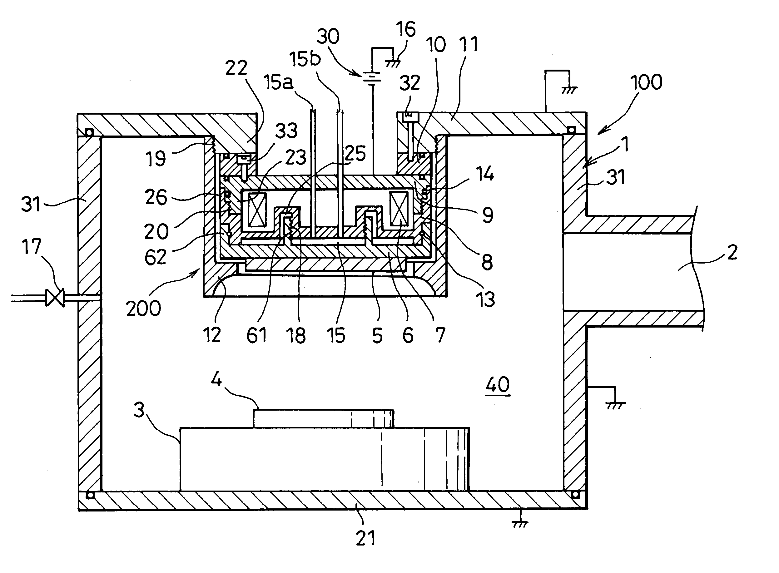
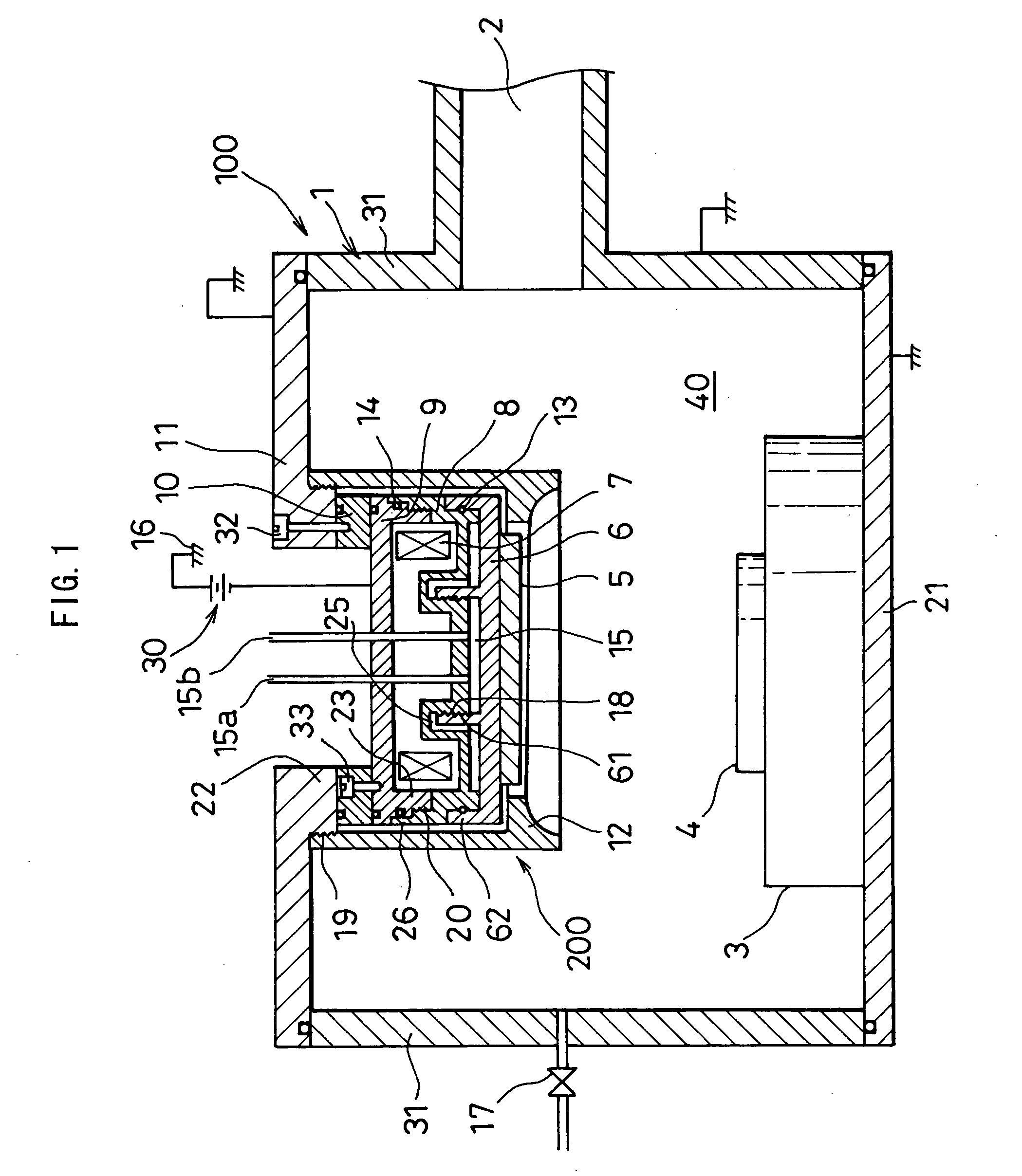
[0013] The following is explained about a working mode of the invention by referring a drawing.

[0014] In a sputtering device 100 according to the working mode of the invention, a vacuum container 1 is constituted of an upper cover 11, side wall portions 31 and a floor portion 21 and defines a vacuum chamber 40 in its inner side. An outlet for vacuum 2 is formed at anyone of the side wall portions 31 of the vacuum container 1, so that gas in the vacuum chamber 40 can be exhausted by a vacuum exhaust pump not shown in a figure. Furthermore, gas supply unit 17 is provided at anyone of the side wall portions 31 of the vacuum container 1, so that a desirable gas such as an argon gas can be introduced into the inner side of the vacuum chamber 40. Besides, the upper cover 11, the side wall portions 31 and the floor portion 21 of the vacuum container 1 are grounded respectively.

[0015] A substrate holder 3 is provided in the vacuum chamber 40 inside the vacuum container 1 and a substrate 4...


PUM

PropertyMeasurementUnit
vacuumaaaaaaaaaa
conductivityaaaaaaaaaa
stabilityaaaaaaaaaa

Abstract

The invention is, for the purpose of putting on or taking off a target and an earth shield easily without spoiling a vacuum condition, to provide a sputtering device comprising at least a vacuum container, a substrate holder installing in said vacuum container, a substrate set on said substrate holder, a target using opposite to said substrate and a sputtering electrode, wherein: said sputtering electrode is constituted of: an electrode base portion having a first screw portion formed on an outer circumferential surface thereof; an electrode body portion having a second screw portion engaging with said first screw portion and having a third screw portion; a back plate portion having: a fourth screw portion engaging with said third screw portion and installing said target; and an earth shield portion provided around said electrode base portion, said electrode body portion and said back plate portion at a specific space.

Description

BACKGROUND OF THE INVENTION [0001] This invention relates to a sputtering device comprising at least a vacuum chamber, a substrate holder installed in the vacuum chamber, a substrate put on the substrate holder, a target using opposite to the substrate, and a sputtering electrode. [0002] Hitherto, as shown in figures of JP H11-36068 A, a cathode unit is screwed to a vacuum chamber by bolts, and parts constituting the cathode unit are fixed with one another by bolts or screws respectively. [0003] As mentioned above, in the prior sputtering device, a back plate on which a target is bonded is changed regularly, but getting-on and taking-off of the back plate is achieved due to getting on or talking off bolts or screws, so that number of man-hour necessary for getting-on and taking-off of the back plate in a device for mass production, in which frequent getting-on and taking-off progress is required, becomes large, because number of bolts or screw is increased when a targets becomes lar...

Claims


Application Information

Patent Timeline
Patent Type & Authority Applications(United States)
IPC IPC(8): H01J37/34H01L21/285C23C14/34
CPCH01J37/3408H01J37/3441H01J37/3435
Inventor TAKAHASHI, NOBUYUKI
Owner CYG CORP
Why Eureka
Try Eureka