Temperatures stable saw sensor with third-order elastic constants

a temperature stable, saw sensor technology, applied in the field of saw sensors, can solve the problems of increasing by 37%, unacceptably large variation in many industrial applications, and not providing a complete temperature stabilization of the torque sensor approach, so as to achieve a low temperature variation and reduce the effect of overall temperature sensitivity

Active Publication Date: 2005-01-06
TRANSENSE TECH
View PDF9 Cites 23 Cited by
  • Summary
  • Abstract
  • Description
  • Claims
  • Application Information

AI Technical Summary

Benefits of technology

[0016] We have now found a means by which the overall temperature sensitivity may be substantially reduced. This desirable characteristic is achieved by reducing the temperature variation of the third order elastic constants of the substrate to a level at which, to a significant extent, they are cancelled out by

Problems solved by technology

However, we have now found that this approach does not provide a complete temperature stabilization of the torque sensor; it works well only when there is no torque applied to the shaft.
For instance, if the two SAW devices

Method used


Image

  • Temperatures stable saw sensor with third-order elastic constants
  • Temperatures stable saw sensor with third-order elastic constants
  • Temperatures stable saw sensor with third-order elastic constants

Examples


Embodiment Construction

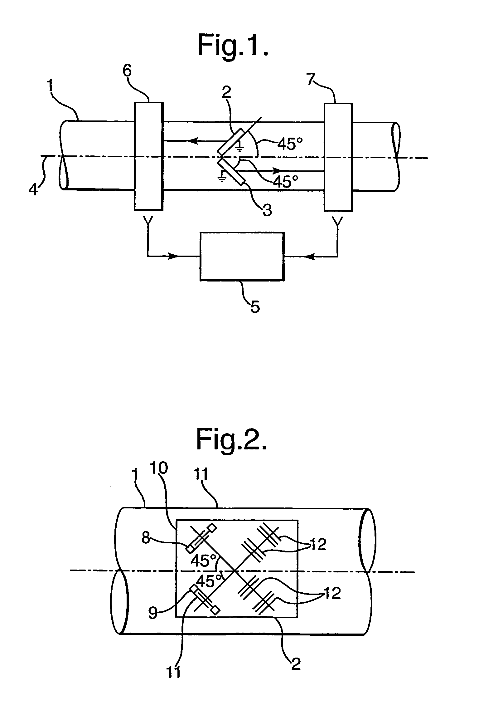
[0029] Referring firstly to FIG. 1, there is illustrated an arrangement for measuring the torque carried by a shaft 1. The arrangement comprises SAW devices 2,3 secured to the surface of the shaft and each oriented at substantially 45° to the axis of rotation 4 of the shaft. The SAW devices comprise separate respective substrates, typically of quartz material, on which are laid down surface conductors to form a surface acoustic wave device. The surface acoustic wave devices may be resonators or delay line devices. The devices are interrogated by an interrogation apparatus 5 via contactless RF connections 6,7. The above arrangement is known. Heretofore, the surface components of the SAW devices were laid down on the substrates so that the direction and propagation of the surface acoustic waves was parallel to the X axis of the ST-cut quartz substrate crystal or the Z axis of Y-cut LiNbO3.

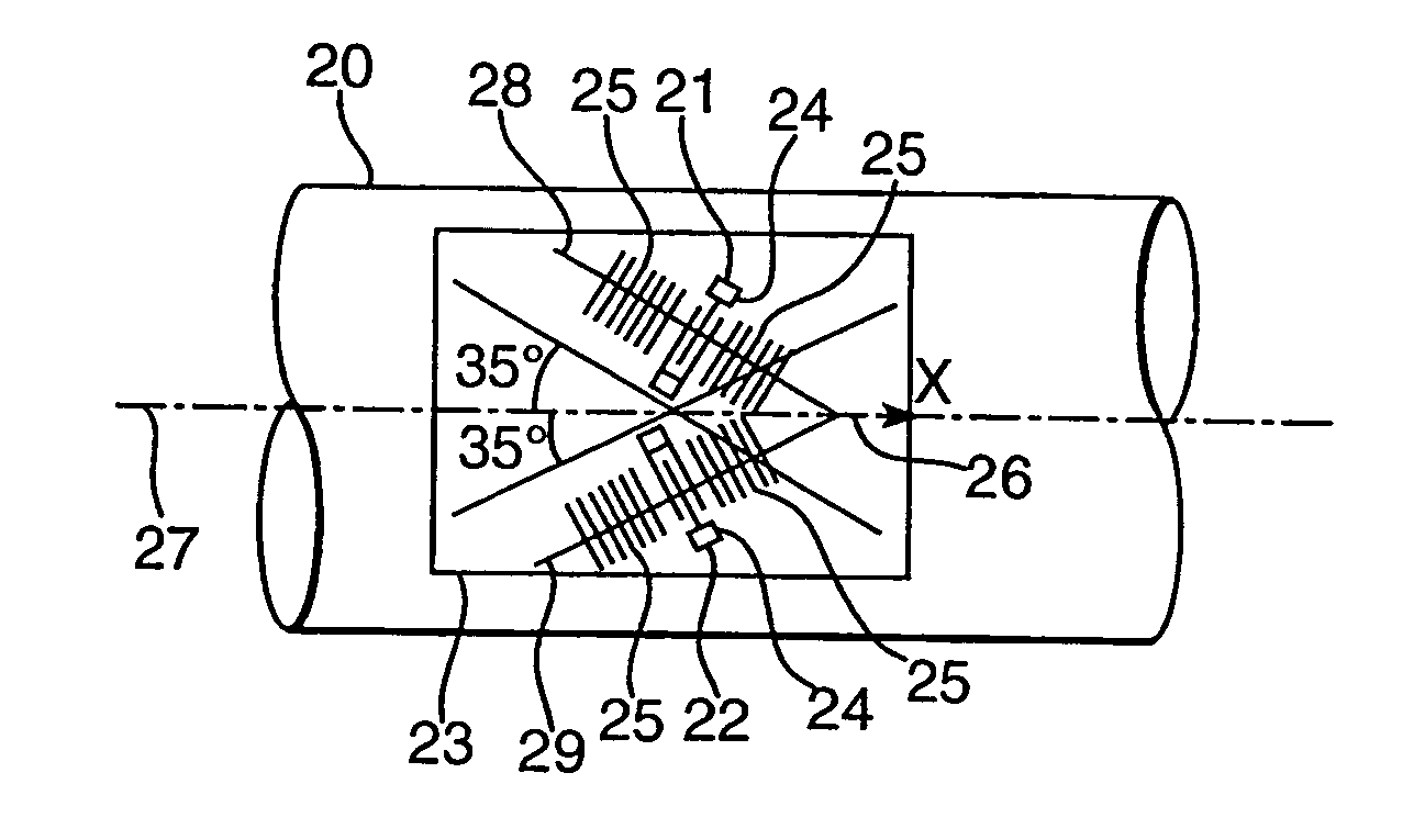
[0030] In the arrangement shown in FIG. 2 two SAW devices 8,9 are laid down on a single quartz s...


PUM


Abstract

A surface acoustic wave (SAW) sensor includes a transducer (240 provided on a substrate (23), wherein the transducer (24) is oriented on the substrate (23) so that the direction of acoustic wave propagation is such that the variation of sensor output with temperature, associated with the variation of the substrate third-elastic constants with temperature, substantially equal but opposite to the sum total of the variation of sensor output with temperature associated with the substrate linear temperature coefficient of expansion and with the variations with temperature of the substrate non-zero third order elastic constants, the substrate first-order elastic constants and the substrate density. The effect of temperature variation on sensor output is thereby minimized. This is achieved with a 35-degree arrangement or with reflective gratings inclined at an angle of 3.1 degrees to normal. Additionally, a robust package with a dish is given. Particular applications include the measurement of torque.

Description

FIELD OF INVENTION [0001] This invention relates to SAW sensors, that is to say sensors which make use of surface acoustic wave (SAW) devices for sensing a physical parameter. DESCRIPTION OF THE RELATED ART [0002] As will be appreciated by those skilled in the art, SAW devices may be used to detect changes in the physical dimensions of the substrate of the SAW device. The resonant frequency of a SAW device (in the case of a SAW resonator) or the group delay or phase delay of a SAW device (in the case of delay line SAW device) varies with changes to the dimensions of the substrate of the SAW device. Accordingly, by arranging the SAW device so that a change in a physical condition produces a change in the dimension of the substrate of the SAW device, the SAW device may be used to provide a measure of the physical condition in question—Typically, SAW devices may be utilized in this manner as strain gauges—One particular application of this technology is the measurement of torque. In th...

Claims


Application Information

Patent Timeline
IPC IPC(8): G01D5/48G01L1/00G01L1/16G01L3/10G01L19/04H01L41/08H01L41/18H03H9/02
CPCG01D5/485G01L3/106H03H9/02834G01L1/165
Inventor KALININ, VICTOR ALEXANDROVICHLEE, MARK
Owner TRANSENSE TECH
Why Eureka
Try Eureka