Electromechanical valve actuator

a technology actuator, which is applied in the direction of non-mechanical valves, magnetic bodies, machines/engines, etc., can solve the problems of difficult to provide fluid to dampers without decreasing the efficiency of electromagnets, noise vibration and harshness, and achieve the effect of improving the durability of electromechanical valve actuators

Inactive Publication Date: 2005-01-06
VISTEON GLOBAL TECH INC
View PDF36 Cites 5 Cited by
  • Summary
  • Abstract
  • Description
  • Claims
  • Application Information

AI Technical Summary

Benefits of technology

[0009] An electromechanical valve actuator for use with an internal combustion engine. The electromechanical valve is formed by molding electromagnets in electromagnet receivers for easy formation and assembly of the electromechanical valve actuator. The molding material may include lubrication passages and cooling passages to improve the durability of the electromechanical valve actuator. A connector may also be integrally molded out of the molding material.

Problems solved by technology

The increase in velocity increases the force of the impact of the armature against the electromagnet, causing noise vibration and harshness concerns.
Due to the impact of the armature plate on a pole face, quiet operation of electromechanical valve actuators may be challenging to achieve.
One problem with fluid energy absorption systems is that it is difficult to provide fluid to the dampers without decreasing the efficiency of the electromagnets.
For example, additional holes drilled into the lamination stack of the electromagnets decreases their efficiency, and such a decrease in efficiency requires additional power to be supplied to the electromagnet to properly and consistently attract the armature plate to the pole face.
Any requirement of additional power puts increased demand on today's already overloaded vehicle electrical systems.
Electromechanical valve actuators also operate in high temperatures with very short cycle times. It is difficult to provide lubrication to armature stems without decreasing the magnetic efficiency of the electromagnets.
Separate oil lines may be added to the top and bottom of the electromechanical valve actuators to provide lubrication to each electromagnet lamination stack, but these oil lines add additional manufacturing costs and assembly time, and increase the package size of the electromechanical valve actuator.
Properly positioning the electromagnets within the c-channels during assembly is difficult due to various tolerance stack ups.
Properly assembling the c-channels into a complete electromechanical valve actuator with the armature plate between the electromagnets so that the pole faces of linear electromagnets are parallel with the armature plate and so that the stem passages in the armature electromagnet and valve electromagnet are aligned is difficult and time consuming.
Any misalignment of the armature stem passage creates excessive wear and friction caused heat.

Method used


Image

  • Electromechanical valve actuator
  • Electromechanical valve actuator
  • Electromechanical valve actuator

Examples


Embodiment Construction

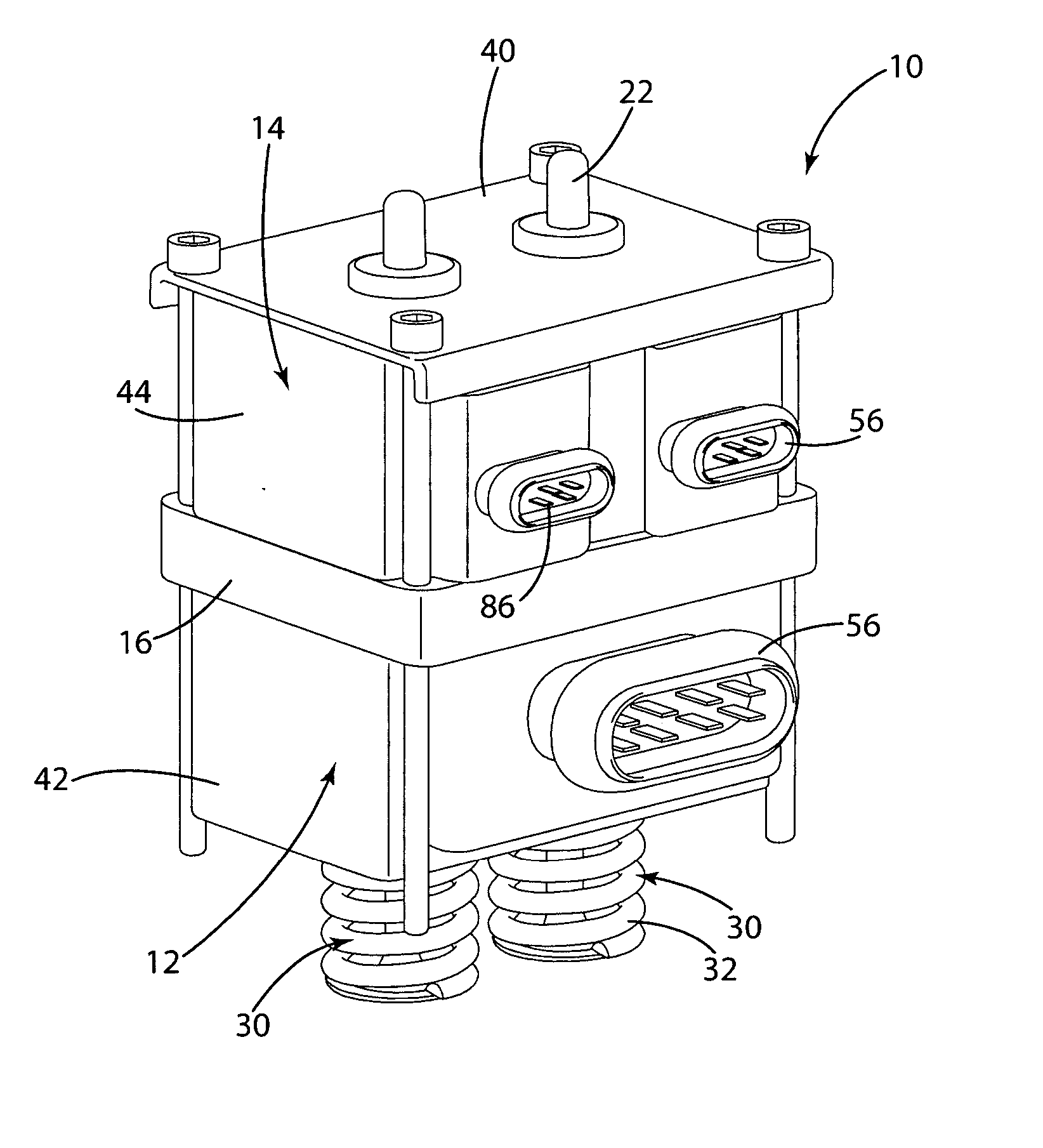
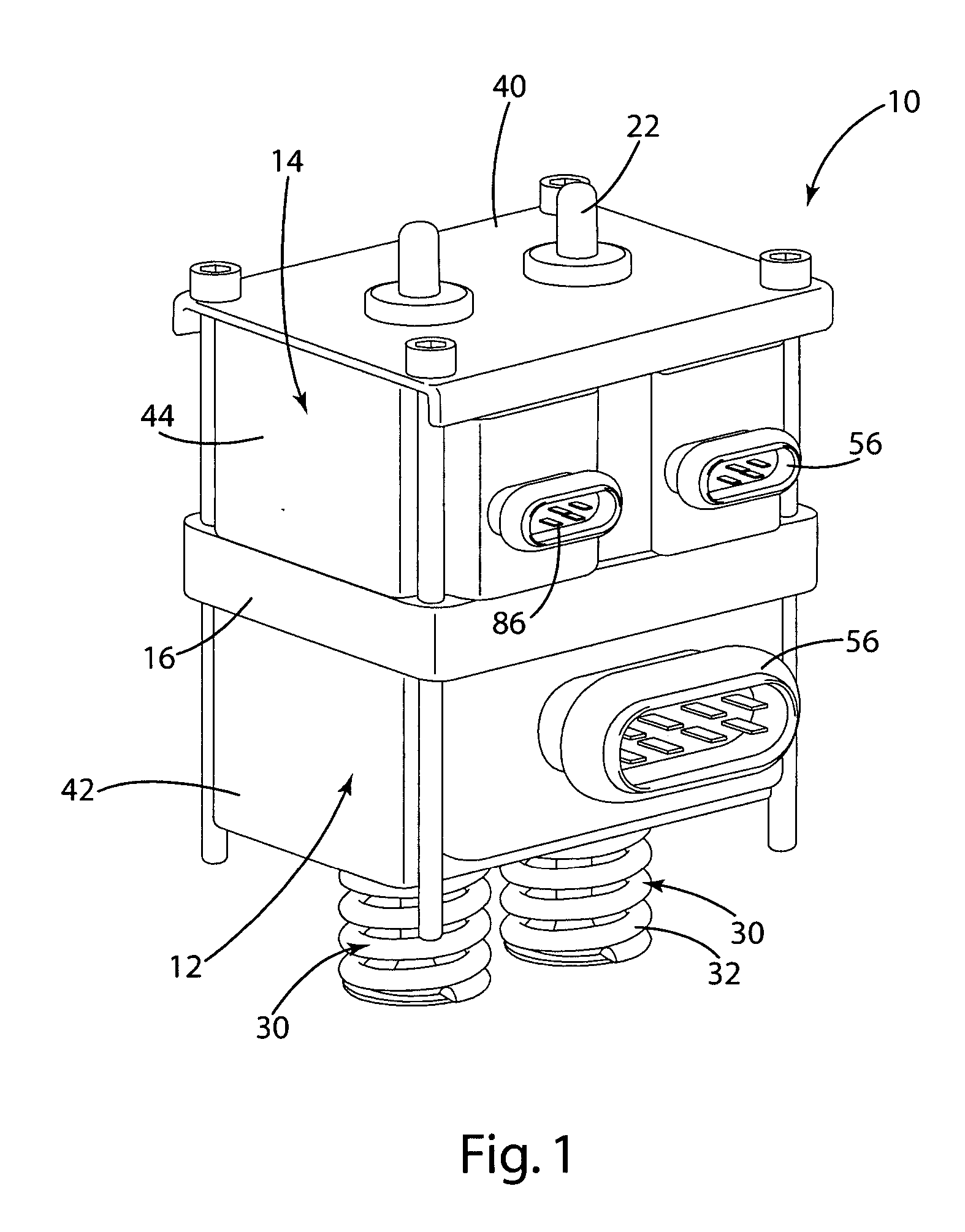
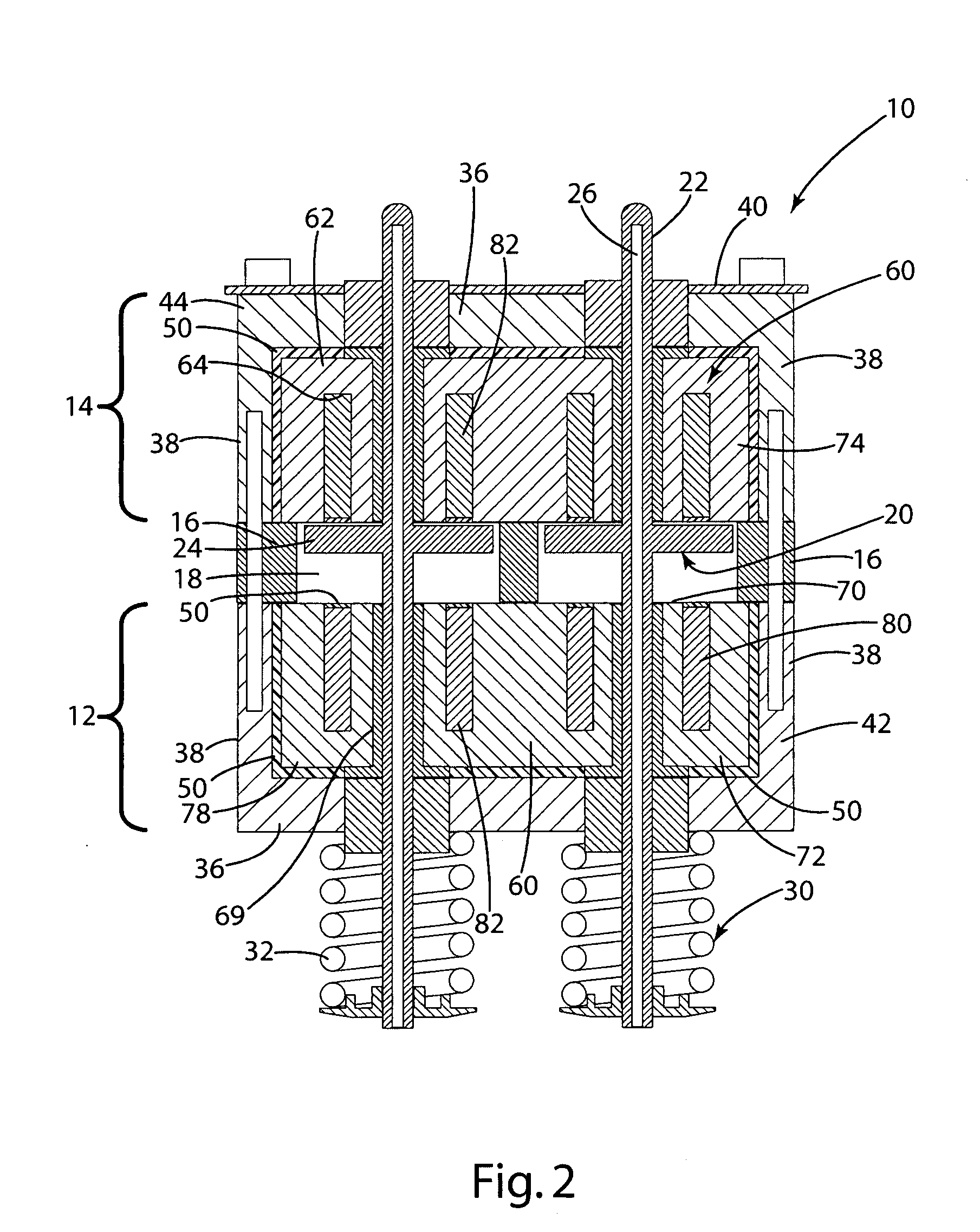
[0028] A linear electromechanical valve actuator 10, typically mounted on an internal combustion engine (not shown) to open and close the valves (e.g. the intake or exhaust valves), is illustrated in FIG. 1. The electromechanical valve actuator 10 generally includes a valve portion 12 separated from an armature portion 14 by a spacer 16. The electromechanical valve actuator 10 further includes an electromagnet assembly 60 having a valve electromagnet 72 and an armature electromagnet 74. The valve portion 12 includes a valve c-channel 42 and the valve electromagnet 74. The armature portion 14 includes an armature c-channel 44 and the armature electromagnet 74. The valve electromagnet 72 and the armature electromagnet 74 are secured within the respective valve channel 42 and armature c-channel 44 with a molding material 50. The molding material 50 allows assembly of the electromechanical valve precisely and efficiently and allows easy changes to the shape and configuration of the elec...


PUM

PropertyMeasurementUnit
electrically insulatingaaaaaaaaaa
heataaaaaaaaaa
swellingaaaaaaaaaa

Abstract

An electromechanical valve actuator for use with an internal combustion engine. The electromechanical valve is formed by molding electromagnets in electromagnet receivers for easy formation and assembly of the electromechanical valve actuator. The molding material may include lubrication passages and cooling passages to improve the durability of the electromechanical valve actuator. A connector may also be integrally molded out of the molding material.

Description

CROSS-REFERENCE TO RELATED APPLICATION [0001] This application claims the benefit of U.S. Provisional Application No. 60 / 479,169, filed Jun. 17, 2003, the entire disclosure of this application being considered part of the disclosure of this application and hereby incorporated by reference.BACKGROUND OF THE INVENTION [0002] The present invention relates to electromechanical valve actuators and a method of assembling electromechanical valve actuators. [0003] As engine technology advances and manufacturers strive to increase engine power, improve fuel economy, decrease emissions, and provide more control over engines, manufacturers are developing electromechanical valve actuators to replace cam shafts for opening and closing engine valves. Electromechanical valve actuators allow selective opening and closing of the valves in response to various engine conditions. [0004] Electromechanical valve actuators generally include two electromagnets formed from a lamination stack and an embedded...

Claims


Application Information

Patent Timeline
Patent Type & Authority Applications(United States)
IPC IPC(8): F01L9/20F01L3/08H01F7/08H01F7/16H01F27/02H01F27/04
CPCF01L3/08F01L9/04F01L2009/0451H01F7/08H01F2007/062H01F7/1638H01F27/022H01F27/04H01F7/081F01L2009/2151F01L9/20
Inventor NORTON, JOHN D.HOPPER, MARK L.NEWTON, STEPHEN J.SMITH, GREG J.SWALES, SHAWN H.
Owner VISTEON GLOBAL TECH INC
Why Eureka
Try Eureka