Image sensor, reading device and method for setting particular mode

Active Publication Date: 2005-01-06
BROTHER KOGYO KK
View PDF7 Cites 5 Cited by
  • Summary
  • Abstract
  • Description
  • Claims
  • Application Information

AI Technical Summary

Benefits of technology

[0033] In the aforementioned method, when the clock pulse signal and the start signal with a fixed width are input, the particular mode setting means sets a particular mode under a specific combination pattern of the clock pulse signal and the start signal. Therefore, in one embodiment of the present invention, because the image sensor does not use signals other than the clock pulse signal and the start signal, and the width of the start signal is fixed at a fixed width, the particular mode can be set. Therefore, the cost can be controlled and a particular mode can be set. Additionally, when setting the particular mode, occurrence of a timing

Problems solved by technology

However, in the conventional technology, it is necessary to input other control signals other than the start signal and the clock pulse signal both of which are dispensable to the control of the shift registers,

Method used


Image

  • Image sensor, reading device and method for setting particular mode
  • Image sensor, reading device and method for setting particular mode
  • Image sensor, reading device and method for setting particular mode

Examples


first embodiment

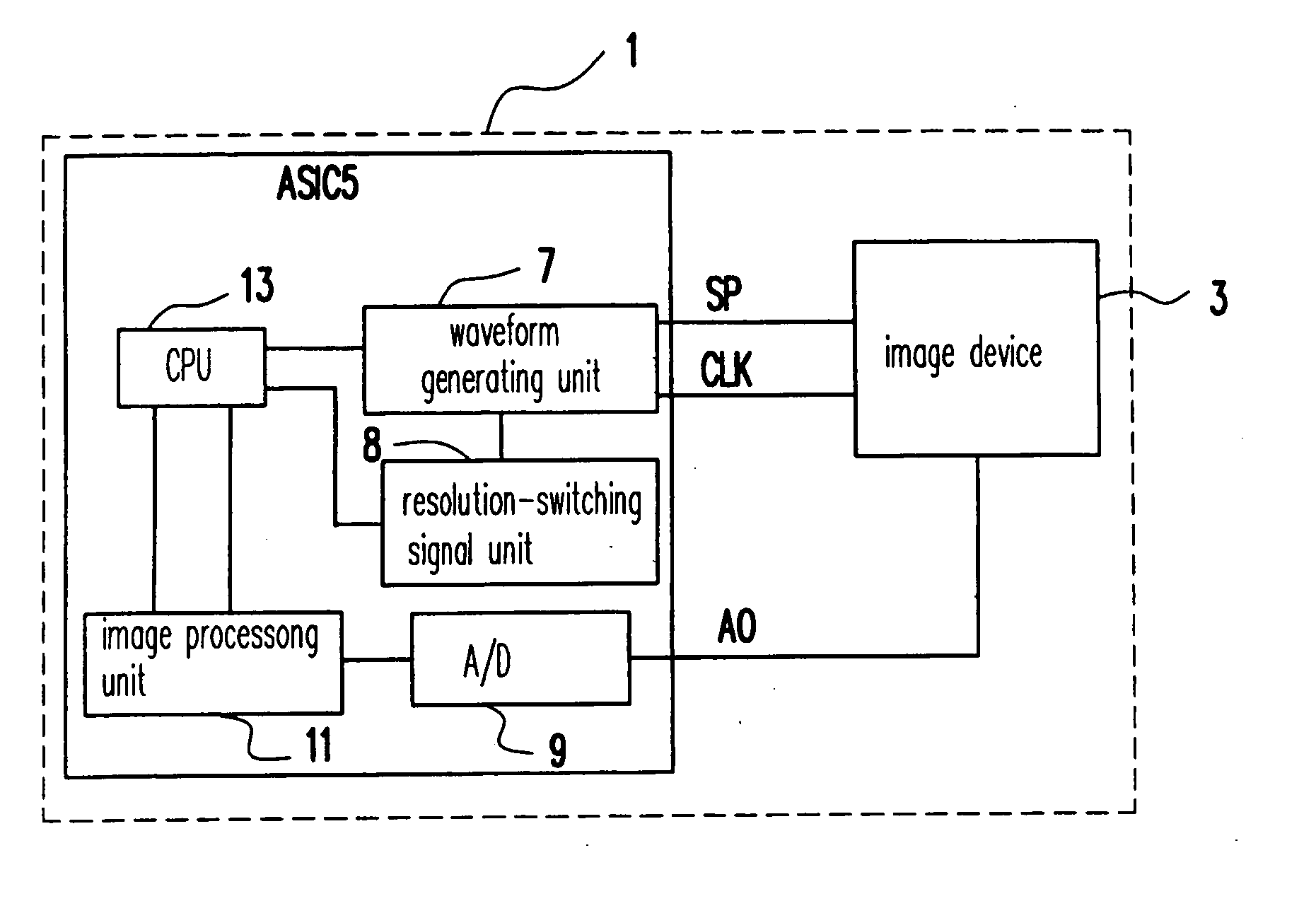
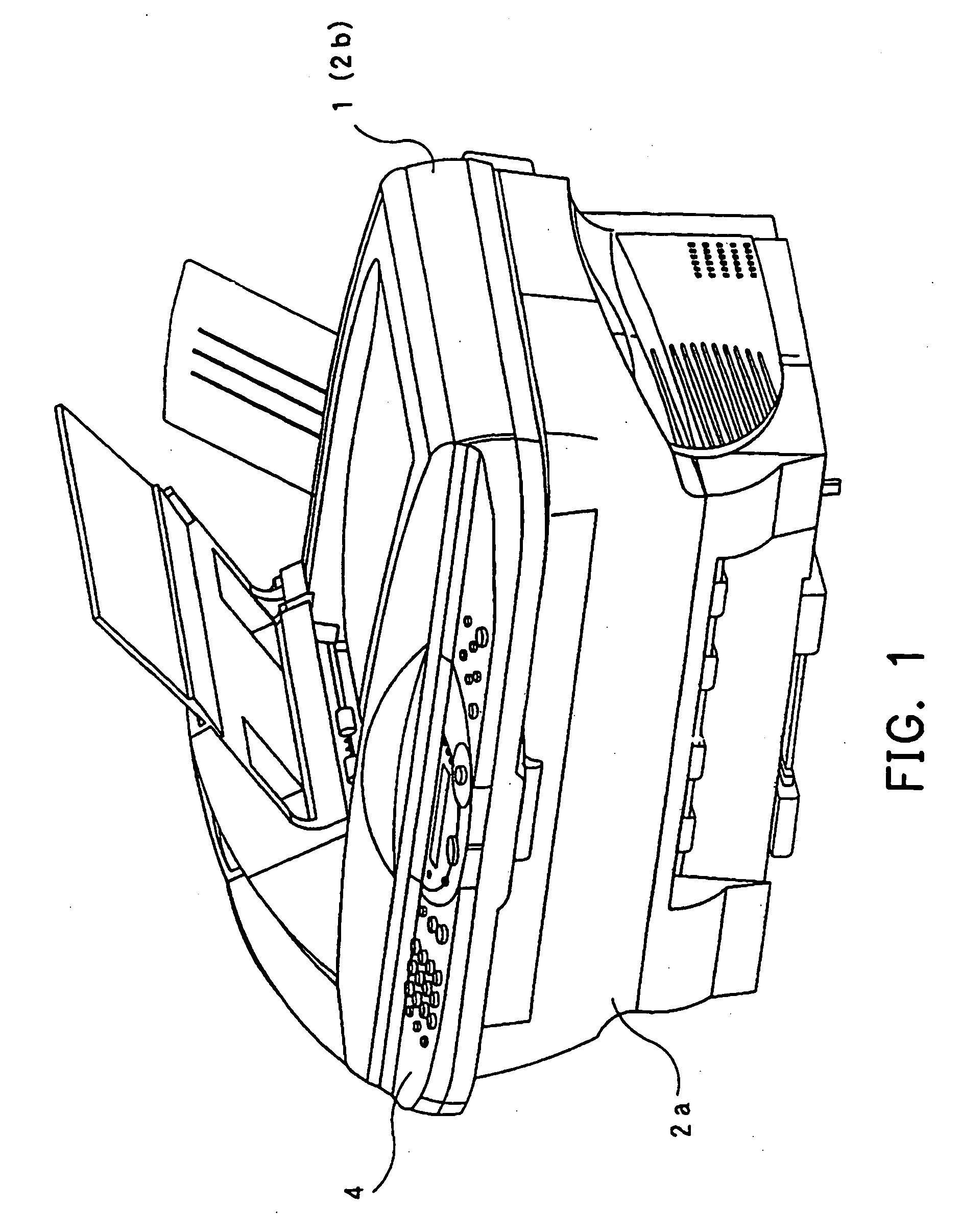
[0050] The image sensor, the reading device and the method for setting the resolution according to the invention will be described in detail hereinafter with reference to the accompanying drawings. FIG. 1 shows an overall structure of a multifunction machine comprising a reading device 1 of the first embodiment is described. The multifunction machine comprises an openable clam-shell mechanism where an upper body 2b is openably assembled to a lower body 2a, and the reading device 1 is included in the upper body 2b. An operation panel 4 is arranged at the front side of the upper body 2b. In addition, the multifunction machine is also equipped with an image forming device, such as a laser printer or an inject printer, etc., but its related description is omitted because there is no direct relationship between them.

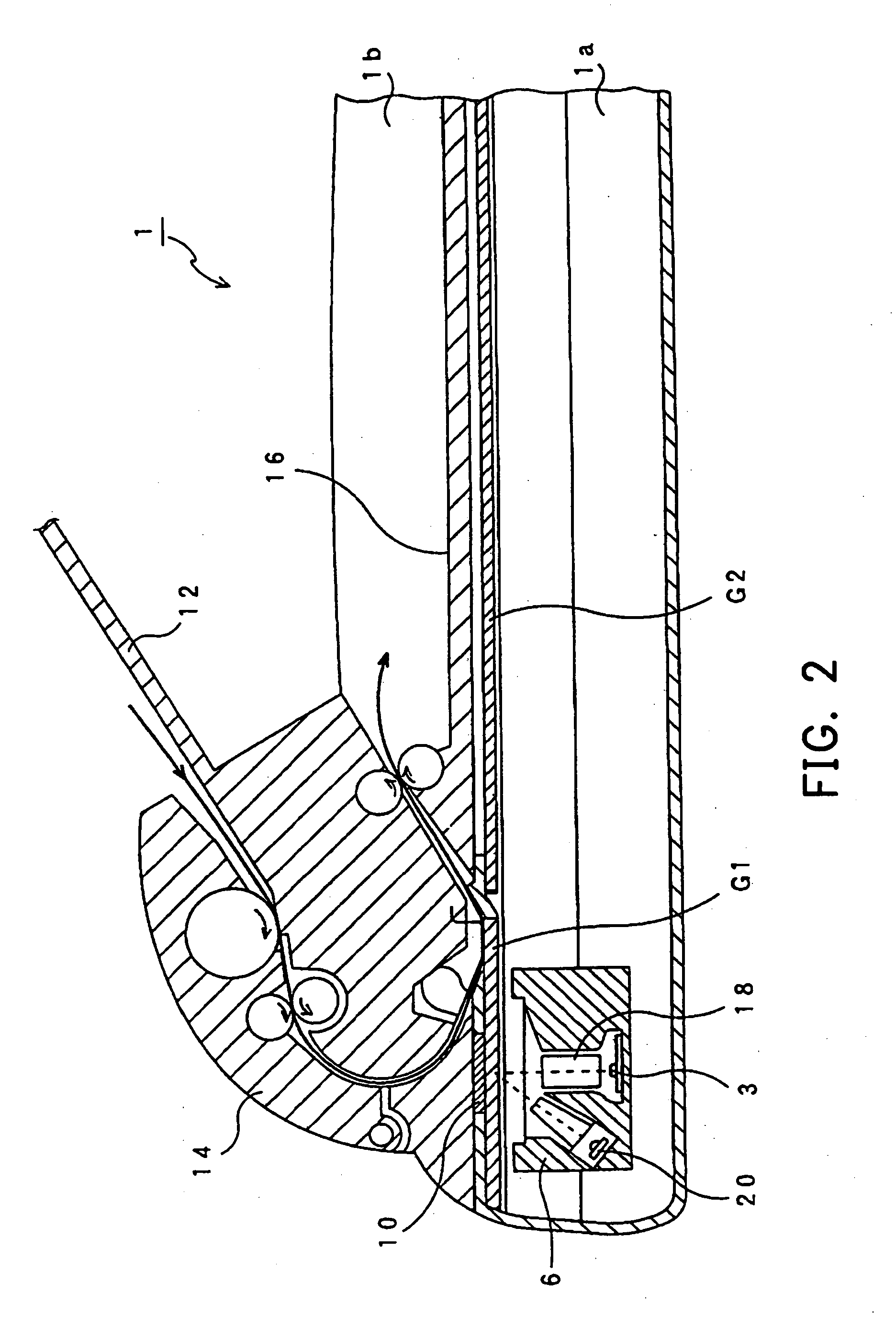
[0051] As shown in FIG. 2, the reading device 1 includes a flat bed (FB) type mechanism and an auto document feed (ADF) type mechanism. The reading device 1 also comprises an...

second embodiment

[0077] In the second embodiment shown in FIG. 9, when the start signal SP detected synchronizing with the rising edges of the clock pulse signal CLK is “H”, “L”, “L” respectively, the resolution is assigned to 1200 dpi. Similarly, “L, H, L” is assigned to 600 dpi, “L, L, H” is assigned to 300 dpi, “H, H, L” is assigned to 150 dpi, “L, H, H” is assigned to 400 dpi, “H, L, H” is assigned to 200 dpi, and “H, H, H” is assigned to 100 dpi.

[0078] In addition, in order to implement resolutions of 400 dpi, 200 dpi, etc., it is necessary to add flip flops (F / F) or other switches to be able to close the analog switches 19 for every three or six switches. Since this structure can be easily modified according to FIG. 5, and therefore a detail description thereof omitted herein. Furthermore, the start signal SP can be also detected synchronizing with the falling edge of the clock pulse signal CLK.

[0079] In the third embodiment shown in FIG. 10, when the start signal SP detected synchronizing wi...

fourth embodiment

[0082] If the mode setting period can also be interrupted at an early stage for a lower resolution as described in the fourth embodiment, the effect can more obvious. Namely, when the resolution is set lower, the user largely hopes a quick output of the image signal more than a lucidity of the read image. Therefore, if the resolution can be affirmatively determined at the early stage of the mode setting period, user's demands can be further satisfied.

[0083] Additionally, in the first embodiment, although the resolution setting is performed for one page at a time (steps S7, S1), the resolution setting of the aforementioned embodiments can be also performed for each line reading in the image. However, the prior case can reduce times of performing the resolution setting, and thus the image reading can be accelerated. Moreover, the resolution setting can be also performed for each job.

[0084]FIGS. 12 and 13 show a block diagram and a timing diagram according to the fifth embodiment of t...


PUM


Abstract

An image sensor, a reading device and a method for setting a particular mode are provided. The image sensor comprises a plurality of photoelectric converting elements, for converting optical signals to electric signals; a group of channel select switches, each channel select switch arranged between a charge output unit of each channel select switch and a signal line corresponding to each photoelectric converting element, wherein the group of the channel select switches can be turned on and off sequentially synchronizing with an externally supplied clock pulse signal; and particular mode setting means, wherein when a clock pulse signal and a start signal with a fixed width are input, the particular mode setting means sets a particular mode under a specific combination pattern of the clock pulse signal and the start signal.

Description

CROSS-REFERENCE TO RELATED APPLICATION [0001] This application claims the priority benefit of Japanese application serial no. 2003-123861, filed on Apr. 28, 2003. BACKGROUND OF THE INVENTION [0002] 1. Field of the Invention [0003] The present invention relates in general to an image sensor, a reading device and a method for setting a particular mode. In particular, the present invention relates to an image sensor, a reading device with the image sensor and a method for setting a particular mode of the image sensor, wherein the image sensor comprises a plurality of photoelectric converting elements for converting light signals into electric signals, and a group of channel select switches between a charge output unit of the photoelectric converting element and a common signal line capable of being sequentially turned on and off. [0004] 2. Description of Related Art [0005] Image sensors are used in a reading device, such as a facsimile, a copy machine and a hand scanner, etc. FIG. 14 s...

Claims


Application Information

Patent Timeline
IPC IPC(8): H01L27/146H04N1/028H04N1/17H04N1/19H04N1/40H04N1/46H04N5/335H04N5/369H04N5/374
CPCH04N1/40056
Inventor KATO, TETSUYANAGASAKA, HIDEAKI
Owner BROTHER KOGYO KK
Why Eureka
Try Eureka