Method and apparatus for controlling modulator phase alignment in a transmitter of an optical communications system

Active Publication Date: 2005-01-06
CIENA
View PDF3 Cites 44 Cited by
  • Summary
  • Abstract
  • Description
  • Claims
  • Application Information

AI Technical Summary

Benefits of technology

[0086] 3) The resolution near the minimum is very good. For a one order of magnitude change in BER (from 4.3 E-9 to 4.1 E-8) we get an 8 dB chang

Problems solved by technology

Over the course of operation, however, components of the transmitter 1 may cause phase drift, resulting in distortion of the CSRZ output. FIG. 2A illustrates proper phase alignment between the CSRZ pulse train and the data stream (represented as a NRZ square waveform in FIG. 2A).
Although CSRZ pulse carver phase can be adjusted manually in the laboratory to visually align the CSRZ pulse train with the data stream by observing the eye diagram of the CSRZ-modulated

Method used


Image

  • Method and apparatus for controlling modulator phase alignment in a transmitter of an optical communications system
  • Method and apparatus for controlling modulator phase alignment in a transmitter of an optical communications system
  • Method and apparatus for controlling modulator phase alignment in a transmitter of an optical communications system

Examples


Embodiment Construction

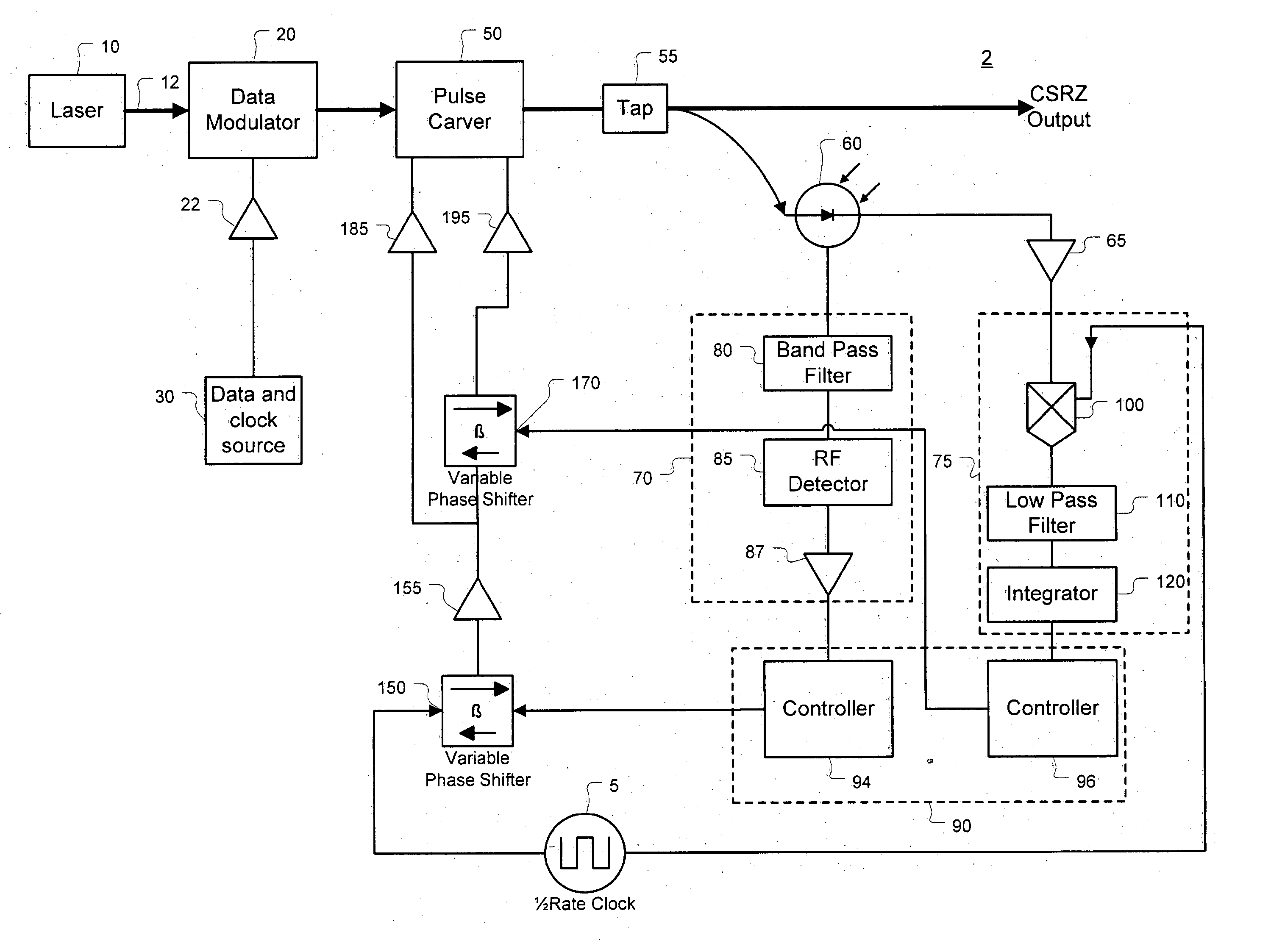
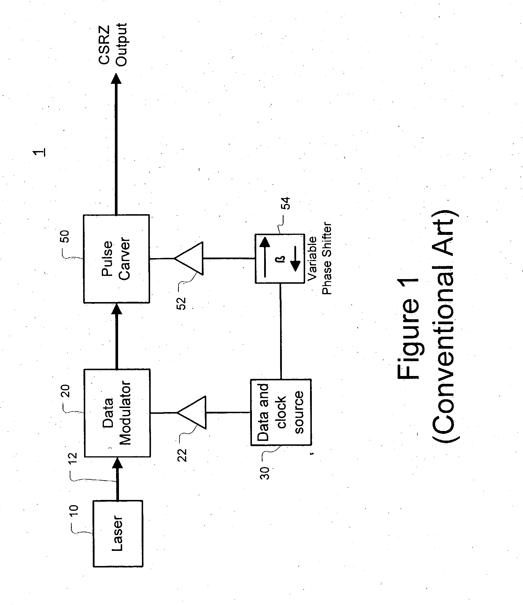
[0032] The present invention is a method and an apparatus for controlling modulator phase alignment in a transmitter of an optical communications system. The following detailed description of the invention refers to the accompanying drawings. The same reference numbers in different drawings identify the same or similar elements. The following detailed description does not limit the invention. Instead, the scope of the invention is defined by the pending claims and equivalents thereof.

[0033] Although the following detailed description uses expressions such as “connected” and “coupled” such terms are used as relative terms and do not require a direct physical connection. For example, the expression “optically coupled” as used herein refers to any connection, coupling, link, or the like by which optical signals are imparted from one optical system element to another. Such “optically coupled” elements are not necessarily directly connected to one another and may be separated by interme...


PUM


Abstract

A method and apparatus for controlling phase alignment in a modulator of a transmitter in an optical communications system utilizes an RF power signature to tune phase alignment. A portion of the optical signal is tapped and converted to an electrical signal. An electrical band-pass filter and RF detector examines a narrow slice of the RF spectrum and utilize the detected RF power to control phase alignment between the data modulator and pulse carver. Another portion of the optical signal is multiplied by the pulse carver clock, filtered and integrated in order to generate a second phase control signal for controlling the relative phase of a dual arm modulator being used as the pulse carver in one embodiment.

Description

FIELD OF THE INVENTION [0001] The present invention relates to a method and apparatus for controlling modulator phase alignment in a transmitter of an optical communications system. DESCRIPTION OF RELATED ART [0002] A transmitter in an optical communications system transmits a data stream by modulating the intensity of light (an optical carrier signal) guided via optical fiber. In existing optical communications systems, a non-return-to-zero (NRZ) modulation scheme, in which a sequence of 1s is transmitted without switching the intensity of the optical carrier signal to zero between each data bit, is commonly used. NRZ modulation utilizes less frequency spectrum as compared to a return-to-zero (RZ) modulation scheme, in which the intensity of the optical carrier signal always returns to zero in between bits of the data stream. Narrower frequency spectrum for modulated data is beneficial for wavelength division multiplexing (WDM) as it reduces crosstalk between the neighboring WDM ch...

Claims


Application Information

Patent Timeline
IPC IPC(8): H04B10/155
CPCH04B10/505H04B10/508H04B10/50577
Inventor SARDESAI, HARSHADSLUZ, STEVE
Owner CIENA
Why Eureka
Try Eureka