Optical discs including equi-radial and/or spiral analysis zones and related disc drive systems and methods

a technology of optical discs and drives, applied in the direction of instruments, liquid chemical processes, pressurized chemical processes, etc., can solve the problems of disc leakage, disc distortion, and various limitations of configuration, and achieve the effect of small sample volume and simple and quick on-disc processing

Inactive Publication Date: 2005-01-06
NAGAOKA
View PDF23 Cites 25 Cited by
  • Summary
  • Abstract
  • Description
  • Claims
  • Application Information

AI Technical Summary

Benefits of technology

[0046] The above described methods and apparatus according to the present invention as disclosed herein can have one or more advantages which include, but are not limited to, simple and quick on-disc processing without the necessity of an experienced technician to run the test, small sample volumes, use of inexpensive materials, and use of known optical disc formats and drive manufacturing. These and other features and advantages will be better understood by reference to the following detailed description when taken in conjunction with the accompanying drawing figures and technical examples.

Problems solved by technology

However, this configuration has various limitations, which are summarized in the following.
Another limitation of the current configuration of the reaction sites is that, in detection mechanisms involving cell capture at a surface, the uncaptured cells move over all other capture regions during disc rotation, and may disturb reactions at these locations.
A still further limitation is that the outer radial portion of a channel of the disc is near the outer edge of the disc itself, leading to the possibility that there may be leakage from the channel out of the disc.

Method used


Image

  • Optical discs including equi-radial and/or spiral analysis zones and related disc drive systems and methods
  • Optical discs including equi-radial and/or spiral analysis zones and related disc drive systems and methods
  • Optical discs including equi-radial and/or spiral analysis zones and related disc drive systems and methods

Examples


Embodiment Construction

[0086] The present invention is directed to disc drive systems, optical bio-discs, image processing techniques, analysis methods, and related software. Each of these aspects of the present invention is discussed below in further detail.

[0087] Drive System and Related Discs

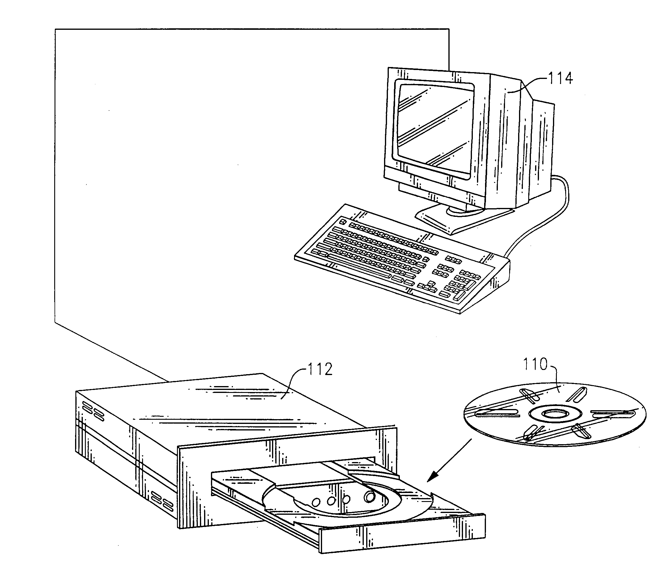
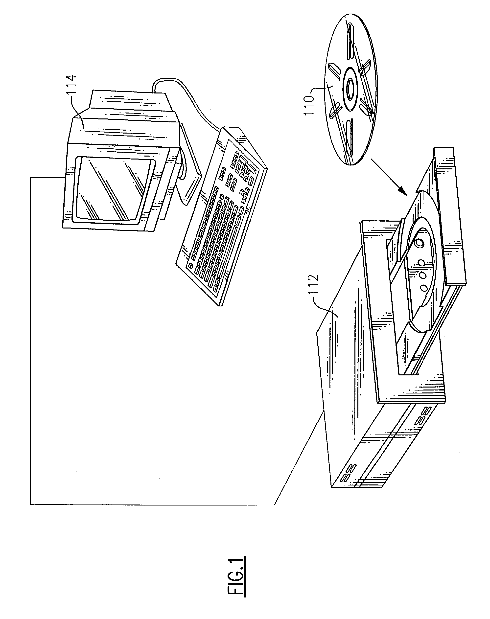
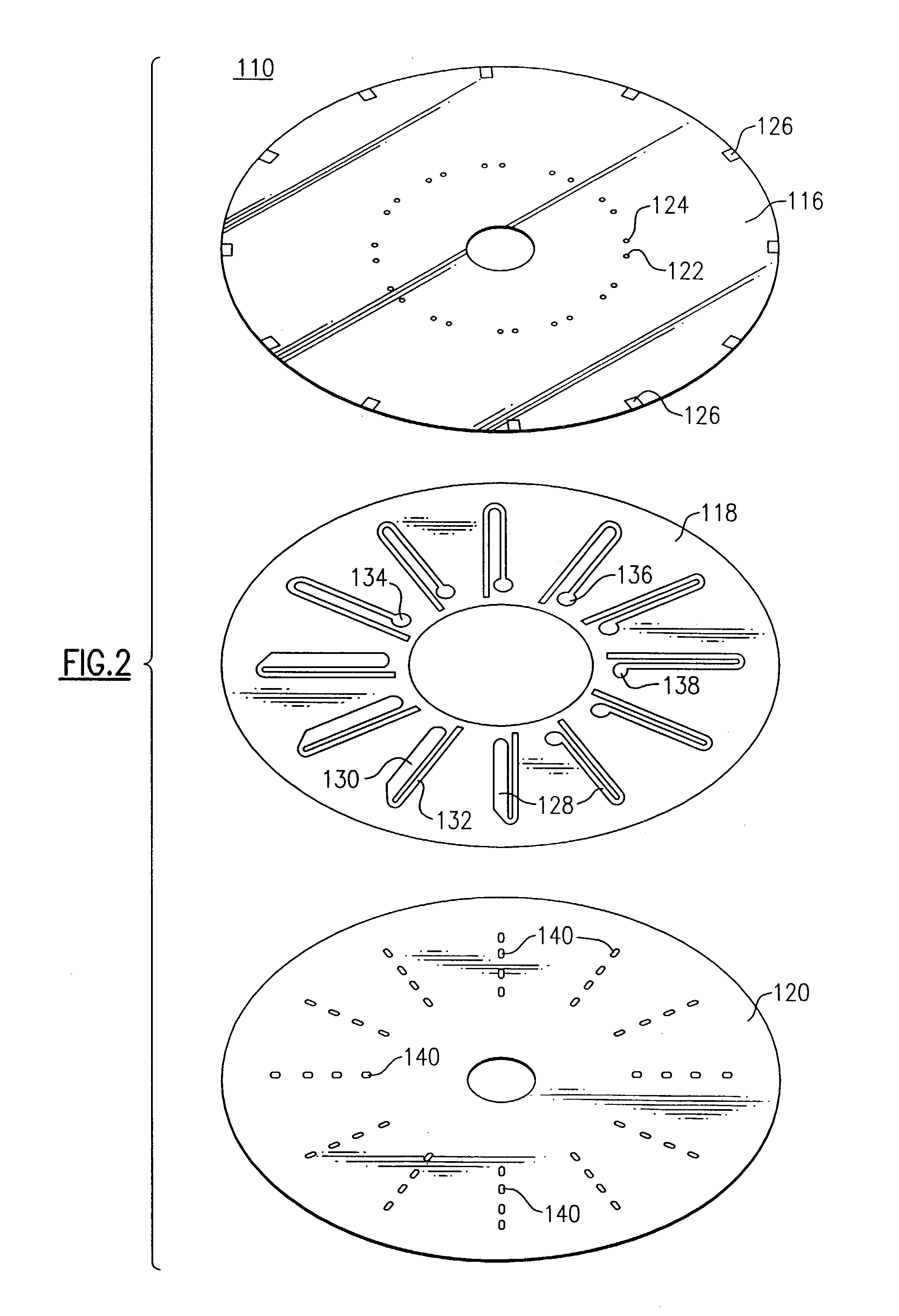
[0088]FIG. 1 is a perspective view of an optical bio-disc 110 for conducting biochemical analyses, and in particular cell counts and differential cell counts. The present optical bio-disc 110 is shown in conjunction with an optical disc drive 112 and a display monitor 114. Further details relating to this type of disc drive and disc analysis system are disclosed in commonly assigned and co-pending U.S. patent application Ser. No. 10 / 008,156 entitled “Disc Drive System and Methods for Use with Bio-discs” filed Nov. 9, 2001 and U.S. patent application Ser. No. 10 / 043,688 entitled “Optical Disc Analysis System Including Related Methods For Biological and Medical Imaging” filed Jan. 10, 2002, both of which are herein...


PUM

PropertyMeasurementUnit
distanceaaaaaaaaaa
thickaaaaaaaaaa
thickaaaaaaaaaa

Abstract

An optical analysis disc includes a substrate having an inner perimeter and an outer perimeter and an operational layer associated with the substrate. The operational layer includes encoded information located substantially along information tracks. An analysis area includes investigational features. The analysis area is positioned between the inner perimeter and the outer perimeter of the substrate and directed along the information tracks so that when an incident beam of electromagnetic energy tracks along the information tracks, any investigational features within the analysis zone are thereby interrogated circumferentially.

Description

CROSS-REFERENCE TO RELATED APPLICATIONS [0001] This application claims the benefit of priority from U.S. Provisional Application Ser. No. 60 / 353,014 filed Jan. 29, 2002 which is herein incorporated by reference in its entirety.STATEMENT REGARDING COPYRIGHTED MATERIAL [0002] Portions of the disclosure of this patent document contain material that is subject to copyright protection. The copyright owner has no objection to the facsimile reproduction by anyone of the patent document or the patent disclosure as it appears in the Patent and Trademark Office file or records, but otherwise reserves all copyright rights whatsoever. BACKGROUND OF THE INVENTION [0003] 1. Field of the Invention [0004] This invention relates in general to optical discs, optical disc drives and optical disc interrogation methods and, in particular, to alternative configurations for the analysis zones of an optical bio-disc. More specifically, but without restriction to the particular embodiments hereinafter descr...

Claims


Application Information

Patent Timeline
Patent Type & Authority Applications(United States)
IPC IPC(8): G01N33/80G01N35/00
CPCG01N35/00069G01N33/80
Inventor MCINTYRE, KEVIN ROBERTCOOMBS, JAMES HOWARD
Owner NAGAOKA
Why Eureka
Try Eureka