Cluster computing system and its failover method

a computing system and cluster computing technology, applied in the field of cluster computing system and its failover method, can solve the problems of inability to check the status of each other, the possibility of all cables being simultaneously disconnected (a total disconnection of the network between sites), and the inability to deny the possibility of all cables being disconnected

Inactive Publication Date: 2005-01-06
HITACHI LTD
View PDF21 Cites 39 Cited by
  • Summary
  • Abstract
  • Description
  • Claims
  • Application Information

AI Technical Summary

Benefits of technology

[0043] The present invention has been conceived to solve the above problem, and relates to a cluster computing system that has an active system and a standby system, and that can operate

Problems solved by technology

The above problem occurs due to the fact that checking the status of counterpart sites in a cluster computing system having a plurality of sites relies on a network between host computers or on a network between storage apparatus systems.
When such network communications are interrupted, the sites are incapable of checking the status of each other.
Howe

Method used


Image

  • Cluster computing system and its failover method
  • Cluster computing system and its failover method
  • Cluster computing system and its failover method

Examples


first embodiment

[0074] Preferred embodiments of the present invention are described below with reference to the accompanying drawings.

[0075] First, a cluster computing system in accordance with a first embodiment of the present invention is described with reference to FIGS. 1 through 15.

[0076] (I) The System Configuration of Cluster Computing System:

[0077] First, referring to FIGS. 1-4, a system configuration of the cluster computing system according to the first embodiment of the present invention is described.

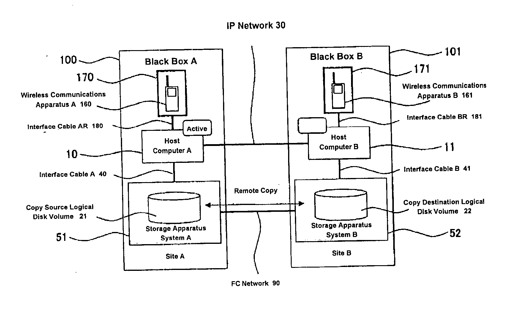
[0078]FIG. 1 is a diagram of the system configuration of a cluster computing system according to the first embodiment of the present invention.

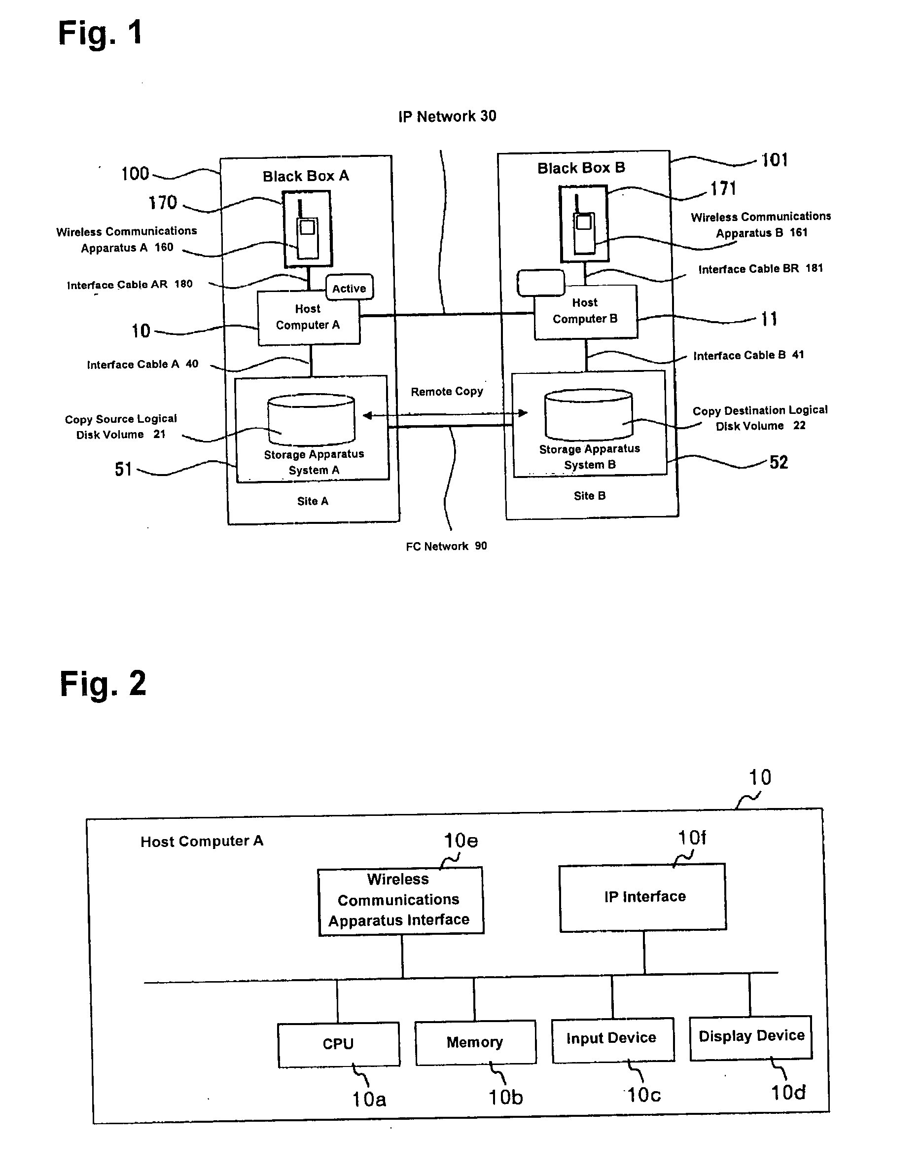
[0079]FIG. 2 is a diagram of the internal configuration of a host computer A.

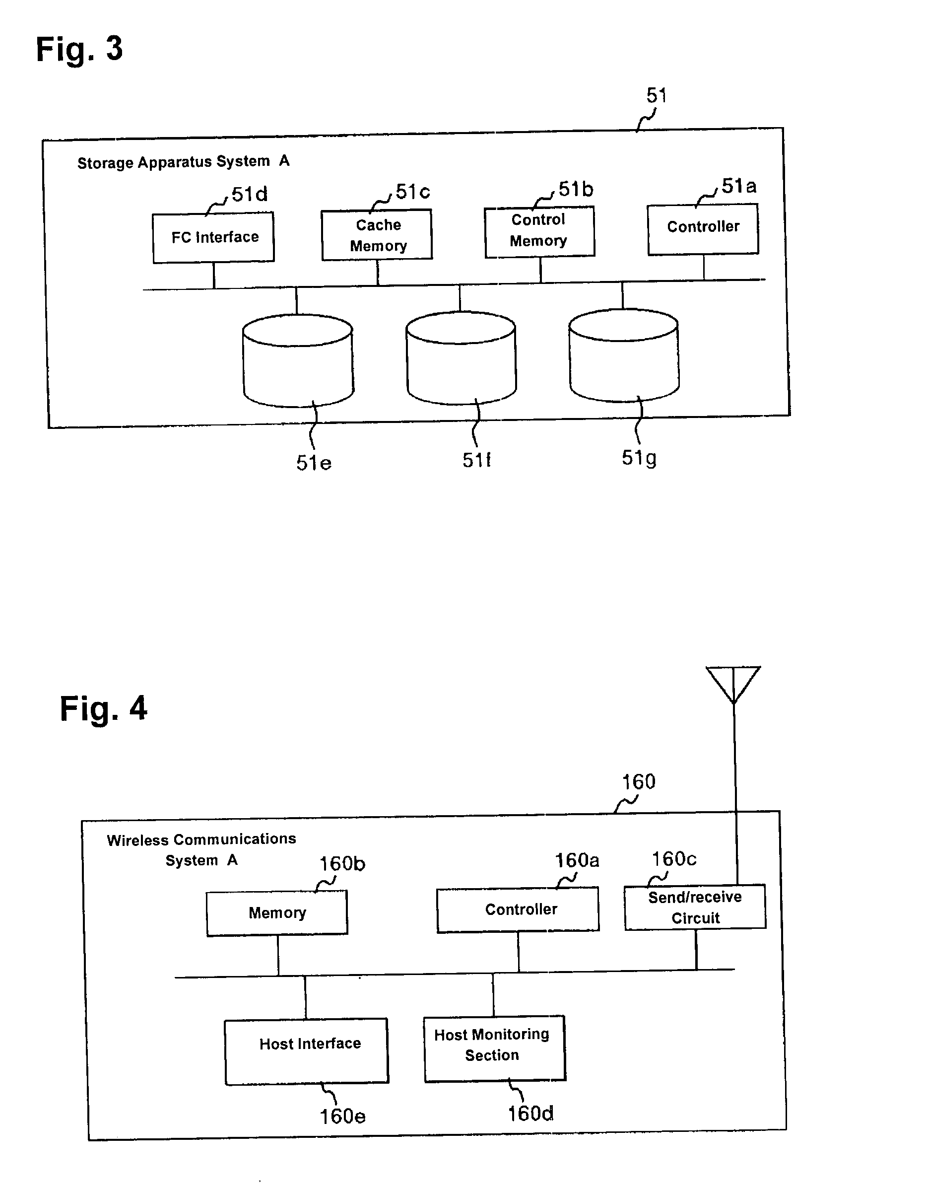
[0080]FIG. 3 is a diagram of the internal configuration of a storage apparatus system A.

[0081]FIG. 4 is a diagram of the internal configuration of a wireless communications apparatus A.

[0082] The cluster computing system in accordance with the first embodiment of the ...

second embodiment

[0175] A cluster computing system in accordance with a second embodiment of the present invention is described below with reference to FIG. 16.

[0176]FIG. 16 is a diagram of a system configuration of the cluster computing system according to the second embodiment of the present invention.

[0177] In the first embodiment, the site A100 and the site B101 had separate storage apparatus systems to perform remote copying.

[0178] In the present embodiment, a site A100 including a wireless communications apparatus A160 and a site B101 including a wireless communications apparatus B161 share a storage apparatus system 50. When a failure occurs at the site A100 in this system configuration, by having the wireless communications apparatus A160 communicate with the wireless communications apparatus B161, communication takes place between an active system and a standby system and failure recovery processing can be performed, as in the first embodiment.

[0179] As described above, according to the...


PUM


Abstract

A cluster computing system includes an active system and a standby system connected via wire networks. The active system and the standby system each has a wireless communications apparatus, such that when all of the wire networks connecting the active system with the standby system are disconnected, the wireless communications apparatus of the active system reports the standby system of the failure of the active system using its wireless communications capability with the wireless communications apparatus of the standby system. The report includes the verification ID of the active system, and the standby system begins operation upon receiving a packet containing the verification ID.

Description

BACKGROUND OF THE INVENTION [0001] 1. Field of the Invention [0002] The present invention relates to a cluster computing system and its failover method, where the cluster computing system is a duplex clustering system that has an active system and a standby system, and that can operate both systems without inconsistencies even in the event of a failure of networks that connect the sites of the two systems and recover from the failure. [0003] 2. Related Background Art [0004] A cluster computing system is a system that operates a plurality of servers as one system in order to enhance the availability and reliability of the system. A function in which an alternate server takes over data and processing in the event of a failure in such a cluster computing system is called a “failover,” which is an important technology in improving the reliability of the system. [0005] Generally, a cluster computing system has one storage apparatus system shared by a plurality of host computers or a plur...

Claims


Application Information

Patent Timeline
IPC IPC(8): G06F13/00G06F11/20G06F15/177H04L69/40
CPCG06F11/20G06F11/2028H04L69/40G06F11/2048G06F11/2038
Inventor HARA, NORIEACHIWA, KYOSUKE
Owner HITACHI LTD
Why Eureka
Try Eureka